Datasheet4U Logo Datasheet4U.com

MC74HCT4052A - Analog Multiplexers/Demultiplexers

Download the MC74HCT4052A datasheet PDF. This datasheet also covers the MC74HCT4051A variant, as both devices belong to the same analog multiplexers/demultiplexers family and are provided as variant models within a single manufacturer datasheet.

Features

  • Fast Switching and Propagation Speeds.
  • Low Crosstalk Between Switches.
  • Diode Protection on All Inputs/Outputs.
  • Analog Power Supply Range (VCC.
  • VEE) = 2.0 to 12.0 V.
  • Digital (Control) Power Supply Range (VCC.
  • GND) = 2.0 to 6.0 V.
  • Improved Linearity and Lower ON Resistance Than Metal.
  • Gate Counterparts.
  • Low Noise.
  • In Compliance with the Requirements of JEDEC Standard No. 7 A.
  • Chip Complexity:.

📥 Download Datasheet

Note: The manufacturer provides a single datasheet file (MC74HCT4051A-ONSemiconductor.pdf) that lists specifications for multiple related part numbers.

Datasheet Details

Part number MC74HCT4052A
Manufacturer onsemi
File Size 332.06 KB
Description Analog Multiplexers/Demultiplexers
Datasheet download datasheet MC74HCT4052A Datasheet

Full PDF Text Transcription (Reference)

The following content is an automatically extracted verbatim text from the original manufacturer datasheet and is provided for reference purposes only.

View original datasheet text
Analog Multiplexers / Demultiplexers with LSTTL Compatible Inputs High−Performance Silicon−Gate CMOS MC74HCT4051A, MC74HCT4052A, MC74HCT4053A 
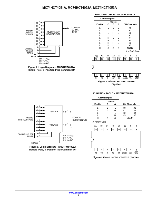
The MC74HCT4051A, MC74HCT4052A and MC74HCT4053A utilize silicon−gate CMOS technology to achieve fast propagation delays, low ON resistances, and low OFF leakage currents. These analog multiplexers/demultiplexers control analog voltages that may vary across the complete power supply range (from VCC to VEE). The HCT4051A, HCT4052A and HCT4053A are identical in pinout to the metal−gate MC14051AB, MC14052AB and MC14053AB. The Channel−Select inputs determine which one of the Analog Inputs/Outputs is to be connected, by means of an analog switch, to the Common Output/Input. When the Enable pin is HIGH, all analog switches are turned off.
Published: |