Datasheet4U Logo Datasheet4U.com

CS1124 - Dual Variable-Reluctance Sensor Interface IC

General Description

br> www.DataSheet4U.com PACKAGE PIN # SO

8 1 2 3 4 5 6 7 8 PIN SYMBOL INAdj IN1 IN2 GND DIAG OUT2 OUT1 VCC FUNCTION External resistor to ground that sets the trip levels of both channels.

Functions for both diagnostic and normal mode.

Input to channel 1.

Key Features

  • es Dual Channel Capability Built.
  • In Test Mode On.
  • Chip Input Voltage Clamping Works from 5.0 V Supply Accurate Built.
  • In Hysteresis VCC PIN.

📥 Download Datasheet

Datasheet Details

Part number CS1124
Manufacturer onsemi
File Size 117.51 KB
Description Dual Variable-Reluctance Sensor Interface IC
Datasheet download datasheet CS1124 Datasheet

Full PDF Text Transcription for CS1124 (Reference)

Note: Below is a high-fidelity text extraction (approx. 800 characters) for CS1124. For precise diagrams, and layout, please refer to the original PDF.

www.DataSheet4U.com 
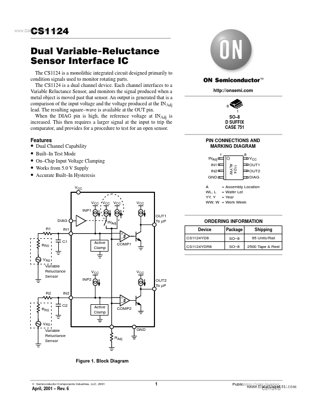
CS1124 Dual Variable-Reluctance Sensor Interface IC The CS1124 is a monolithic integrated circuit designed primarily to condition signals used to moni...

View more extracted text
ntegrated circuit designed primarily to condition signals used to monitor rotating parts. The CS1124 is a dual channel device. Each channel interfaces to a Variable Reluctance Sensor, and monitors the signal produced when a metal object is moved past that sensor. An output is generated that is a comparison of the input voltage and the voltage produced at the IN Adj lead. The resulting square–wave is available at the OUT pin. When the DIAG pin is high, the reference voltage at INAdj is increased. This then requires a larger signal at the input to trip the comparator, and provides for a procedure to test for an open sensor.