Datasheet Details
| Part number | 74LS256 |
|---|---|
| Manufacturer | National Semiconductor (Texas Instruments) |
| File Size | 118.21 KB |
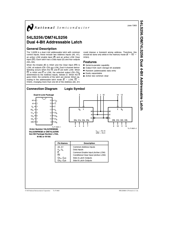
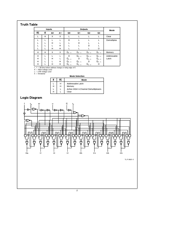
| Description | Dual 4-Bit Addressable Latch |
| Datasheet |
 74LS256 Datasheet 74LS256 Datasheet
|
|
|
| Part number | 74LS256 |
|---|---|
| Manufacturer | National Semiconductor (Texas Instruments) |
| File Size | 118.21 KB |
| Description | Dual 4-Bit Addressable Latch |
| Datasheet |
74LS256 Datasheet
|
|
|
|
| Part Number | Description | Manufacturer |
|---|---|---|
| 74LS256 | Dual 4-Bit Addressable Latch | Signetics |
| 74LS256 | DUAL 4-BIT ADDRESSABLE LATCH | Motorola |
| 74LS251 | LOW POWER SCHOTTKY | ON Semiconductor |
| 74LS251 | 3-STATE 1-of-8 Line Data Selector/Multiplexer | Fairchild Semiconductor |
| 74LS251 | 1 of 8 Data Selectors/Multiplexers | Hitachi Semiconductor |
| Part Number | Description |
|---|---|
| 74LS257 | TRI-STATE Quad 2-Data Selectors/Multiplexers |
| 74LS257B | Quad 2-Data Selectors/Multiplexers |
| 74LS258B | Quad 2-Data Selectors/Multiplexers |
| 74LS20 | Dual 4-Input NAND Gates |
| 74LS240 | Octal TRI-STATE Buffers/Line Drivers/Line Receivers |
The following content is an automatically extracted verbatim text from the original manufacturer datasheet and is provided for reference purposes only.