The following content is an automatically extracted verbatim text
from the original manufacturer datasheet and is provided for reference purposes only.
View original datasheet text
MOTOROLA
SEMICONDUCTOR TECHNICAL DATA
Order this document by MRF9100/D
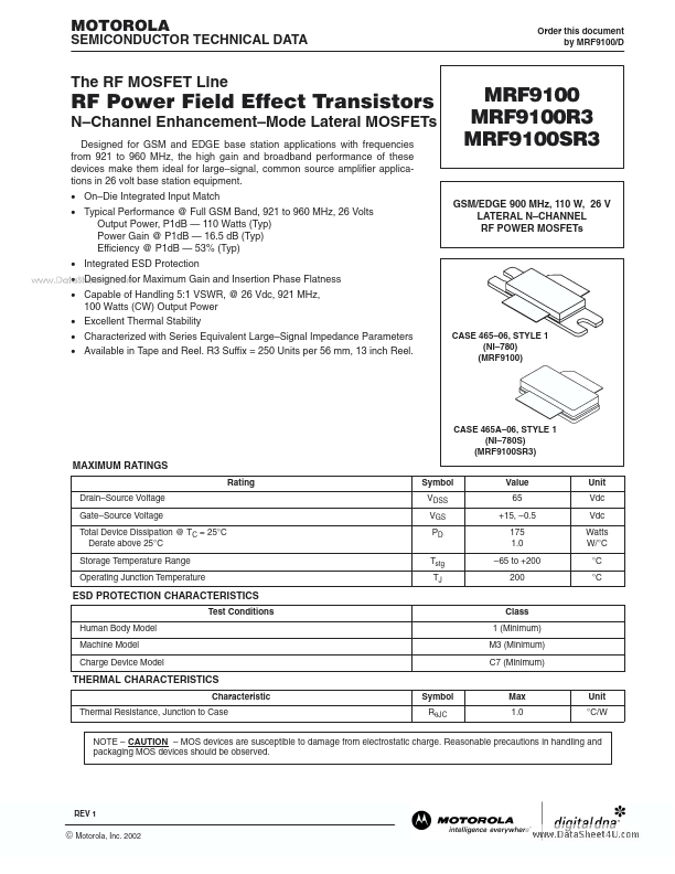
The RF MOSFET Line
RF Power Field Effect Transistors
N–Channel Enhancement–Mode Lateral MOSFETs
Designed for GSM and EDGE base station applications with frequencies from 921 to 960 MHz, the high gain and broadband performance of these devices make them ideal for large–signal, common source amplifier applications in 26 volt base station equipment. • On–Die Integrated Input Match • Typical Performance @ Full GSM Band, 921 to 960 MHz, 26 Volts Output Power, P1dB — 110 Watts (Typ) Power Gain @ P1dB — 16.5 dB (Typ) Efficiency @ P1dB — 53% (Typ) • Integrated ESD Protection • Designed for Maximum Gain and Insertion Phase Flatness www.DataSheet4U.
 MRF9100 Datasheet