The following content is an automatically extracted verbatim text
from the original manufacturer datasheet and is provided for reference purposes only.
View original datasheet text
MOTOROLA
SEMICONDUCTOR TECHNICAL DATA
Order this document by MRF5003/D
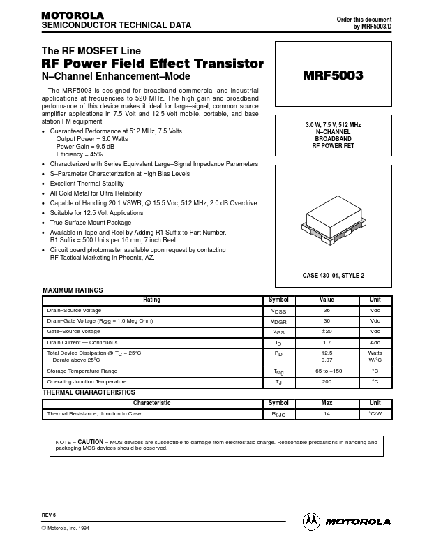
The RF MOSFET Line
RF Power Field Effect Transistor
N–Channel Enhancement–Mode
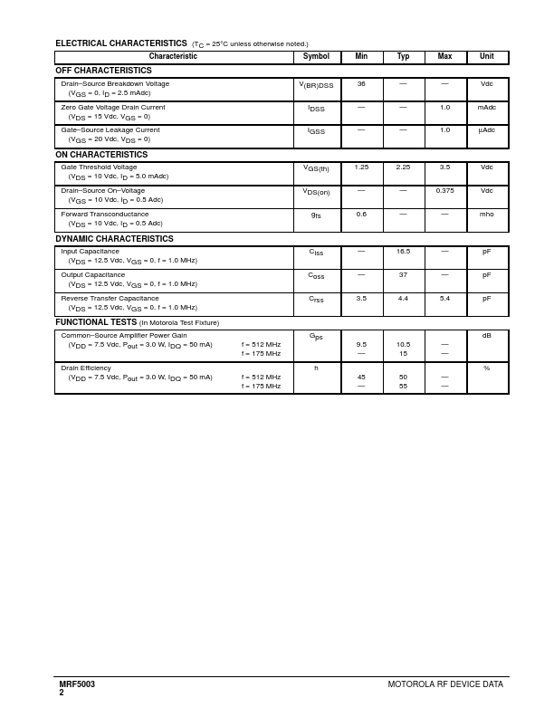
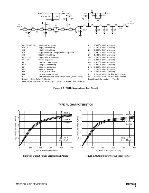
The MRF5003 is designed for broadband commercial and industrial applications at frequencies to 520 MHz. The high gain and broadband performance of this device makes it ideal for large–signal, common source amplifier applications in 7.5 Volt and 12.5 Volt mobile, portable, and base station FM equipment. • Guaranteed Performance at 512 MHz, 7.5 Volts Output Power = 3.0 Watts Power Gain = 9.5 dB Efficiency = 45% • Characterized with Series Equivalent Large–Signal Impedance Parameters • S–Parameter Characterization at High Bias Levels • Excellent Thermal Stability • All Gold Metal for Ultra Reliability • Capable of Handling 20:1 VSWR, @ 15.
 MRF5003 Datasheet