Datasheet4U Logo Datasheet4U.com

MRF284S - RF Power Field-Effect Transistors

Download the MRF284S datasheet PDF. This datasheet also covers the MRF284 variant, as both devices belong to the same rf power field-effect transistors family and are provided as variant models within a single manufacturer datasheet.

Features

  • 0 13 IDQ = 400 mA G pe , POWER GAIN (dB) 12 300 mA.
  • 30 200 mA 11 10 9 100 mA 8 0.1 VDD = 26 Vdc f1 = 2000.0 MHz f2 = 2000.1 MHz 1.0 10 Pout, OUTPUT POWER (WATTS) PEP Pout, OUTPUT POWER (WATTS) PEP Figure 7. Intermodulation Distortion versus Output Power Figure 8. Power.

📥 Download Datasheet

Note: The manufacturer provides a single datasheet file (MRF284_Motorola.pdf) that lists specifications for multiple related part numbers.

Full PDF Text Transcription (Reference)

The following content is an automatically extracted verbatim text from the original manufacturer datasheet and is provided for reference purposes only.

View original datasheet text
www.DataSheet4U.com 
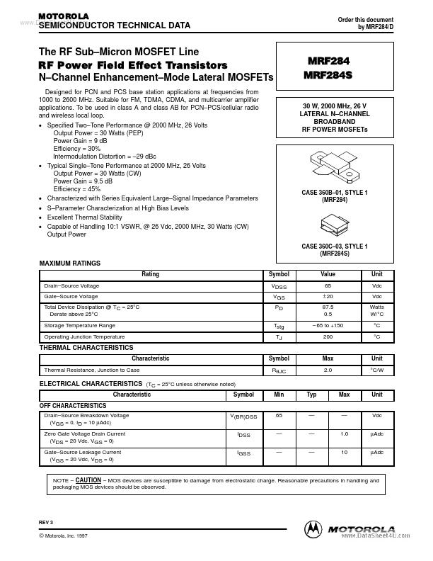
MOTOROLA SEMICONDUCTOR TECHNICAL DATA Order this document by MRF284/D The RF Sub–Micron MOSFET Line RF Power Field Effect Transistors N–Channel Enhancement–Mode Lateral MOSFETs Designed for PCN and PCS base station applications at frequencies from 1000 to 2600 MHz. Suitable for FM, TDMA, CDMA, and multicarrier amplifier applications. To be used in class A and class AB for PCN–PCS/cellular radio and wireless local loop. • Specified Two–Tone Performance @ 2000 MHz, 26 Volts Output Power = 30 Watts (PEP) Power Gain = 9 dB Efficiency = 30% Intermodulation Distortion = –29 dBc • Typical Single–Tone Performance at 2000 MHz, 26 Volts Output Power = 30 Watts (CW) Power Gain = 9.