Datasheet4U Logo Datasheet4U.com

MC145408 - DRIVER/RECEIVERS

Download the MC145408 datasheet PDF. This datasheet also covers the MC145403 variant, as both devices belong to the same driver/receivers family and are provided as variant models within a single manufacturer datasheet.

Description

VCC Digital Power Supply The digital supply pin, which is connected to the logic power supply (+ 5.5 V maximum).

232

E connector (Pin 7) as well as to the logic power supply ground.

Features

  • Drivers.
  • ± 5 to ± 12 V Supply Range 300 Ω Power.
  • Off Source Impedance Output Current Limiting TTL and CMOS Compatible Inputs Driver Slew Rate Range Limited to 30 V/µs Maximum ± 25 V Input Range 3 to 7 kΩ Input Impedance 0.8 V of Hysteresis for Enhanced Noise Immunity TTL and CMOS Compatible Outputs 24 24 1 20 1 P SUFFIX.

📥 Download Datasheet

Note: The manufacturer provides a single datasheet file (MC145403_Motorola.pdf) that lists specifications for multiple related part numbers.

Full PDF Text Transcription (Reference)

The following content is an automatically extracted verbatim text from the original manufacturer datasheet and is provided for reference purposes only.

View original datasheet text
www.DataSheet4U.com MOTOROLA SEMICONDUCTOR TECHNICAL DATA Order this document by MC145403/D 
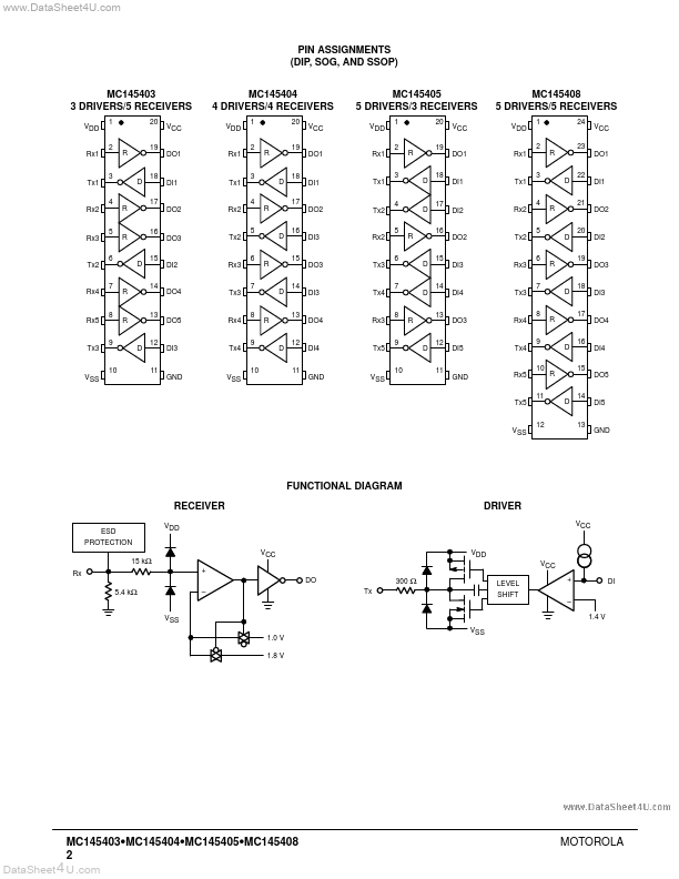
MC145403 Drivers/Receivers MC145404 MC145405 MC145408 EIA–232–E and CCITT V.28 These devices are silicon gate CMOS ICs that combine both the transmitter and receiver to fulfill the electrical specifications of EIA Standard 232–E and CCITT V.28. The drivers feature true TTL input compatibility, slew rate limiting outputs, 300 Ω power–off source impedance, and output typically switching to within 25% of the supply rails. The receivers can handle up to ± 25 V while presenting 3 to 7 kΩ impedance. Hysteresis in the receivers aid in the reception of noisy signals.
Published: |