• Part: 1N6381
  • Description: Zener Transient Voltage Suppressors
  • Manufacturer: Motorola Semiconductor
  • Size: 81.41 KB
Download 1N6381 Datasheet PDF
Motorola Semiconductor
1N6381
1N6381 is Zener Transient Voltage Suppressors manufactured by Motorola Semiconductor.
- Part of the 1N6383 comparator family.
Features : Standard Voltage Range - 6.2 to 250 V Peak Power - 1500 Watts @ 1 ms Maximum Clamp Voltage @ Peak Pulse Current Low Leakage < 5 µA Above 10 V UL Recognition Response Time is Typically < 1 ns CASE 41A PLASTIC Mechanical Characteristics: CASE: Void-free, transfer-molded, thermosetting plastic FINISH: All external surfaces are corrosion resistant and leads are readily solderable POLARITY: Cathode indicated by polarity band. When operated in zener mode, will be positive with respect to anode MOUNTING POSITION: Any WAFER FAB LOCATION: Phoenix, Arizona ASSEMBLY/TEST LOCATION: Guadalajara, Mexico MAXIMUM RATINGS Rating Peak Power Dissipation (1) @ TL ≤ 25°C Steady State Power Dissipation @ TL ≤ 75°C, Lead Length = 3/8″ Derated above TL = 75°C Forward Surge Current (2) @ TA = 25°C Operating and Storage Temperature Range Lead temperature not less than 1/16″ from the case for 10 seconds: 230°C NOTES: 1. 
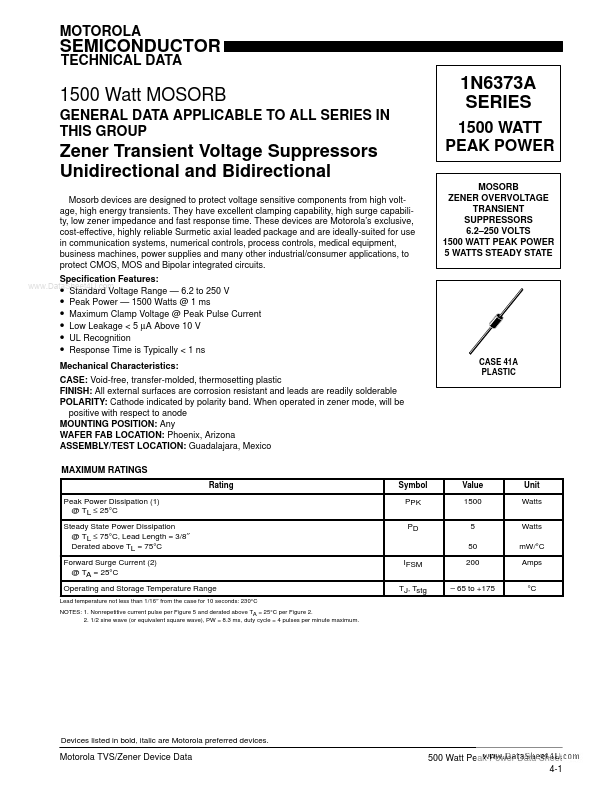
Nonrepetitive current pulse per Figure 5 and derated above TA = 25°C per Figure 2. NOTES: 2. 1/2 sine wave (or equivalent square wave), PW = 8.3 ms, duty cycle = 4 pulses per minute maximum. Symbol PPK PD Value 1500 5 50 Unit Watts Watts m W/°C Amps °C IFSM TJ, Tstg - 65 to +175 Devices listed in bold, italic are Motorola preferred devices. Motorola TVS/Zener Device Data 500 Watt Peak Power Data Sheet 4-1 - ELECTRICAL CHARACTERISTICS (TA = 25°C unless otherwise noted) VF# = 3.5 V Max, IF- - = 100 A) (C suffix denotes standard ELECTRICAL CHARACTERISTICS back to back bidirectional versions. Test both polarities) Maximum Reverse Voltage Maximum @ IRSM{ Reverse M i Maximum (Clamping Surge Reverse Voltage) Current Leakage VRSM IRSM{ @ VRWM (Volts) (Amps) IR (µA) Clamping Voltage Peak Pulse Current @ Ipp1{ = 1 A VC1 (Volts max) Peak Pulse Current @ Ipp1{ = 10 A VC2 (Volts max) Breakdown{{ Voltage JEDEC Device Note 1 VBR Volts Min Device Note 1 @ IT (m A) Maximum Reverse Stand-Off Voltage VRWM- - - (Volts) 1N6373 1N6374 1N6382 1N6375 1N6383 1N6376...