Datasheet4U.com
🌙
CM100E3U-12H Mitsubishi Electric Datasheet
Part:
CM100E3U-12H
Description:
IGBT Module
Manufacturer:
Mitsubishi Electric
Size:
50.79 KB
Download CM100E3U-12H Datasheet PDF
Page 2
Page 3
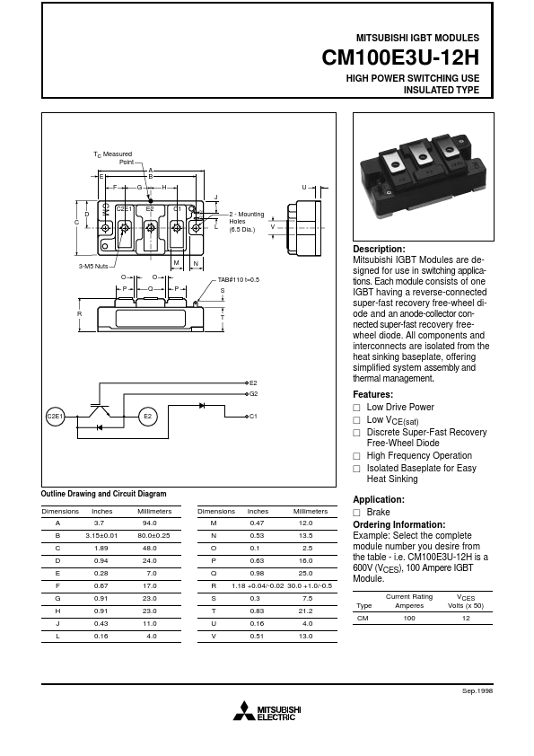
CM100E3U-12H Key Features
i.e. CM100E3U-12H is a 600V (VCES), 100 Ampere IGBT Module
Other CM100E3U-12H Datasheets
Manufacturer
Part Number
Description
Powerex, Inc
CM100E3U-12H
IGBT Module
View all CM100E3U-12H datasheets →
×
Close