Part number:
CM1000HA-24H
Manufacturer:
Mitsubishi Electric Semiconductor
File Size:
49.55 KB
Description:
Igbt module.
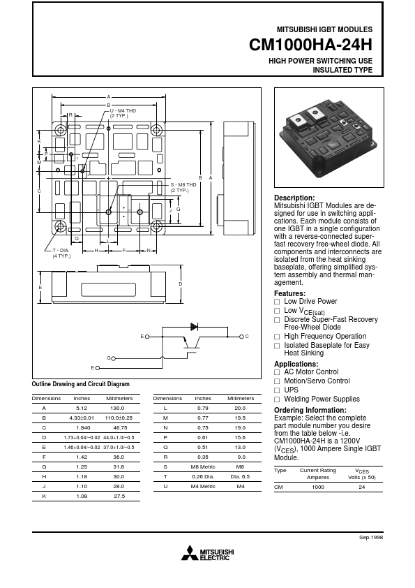
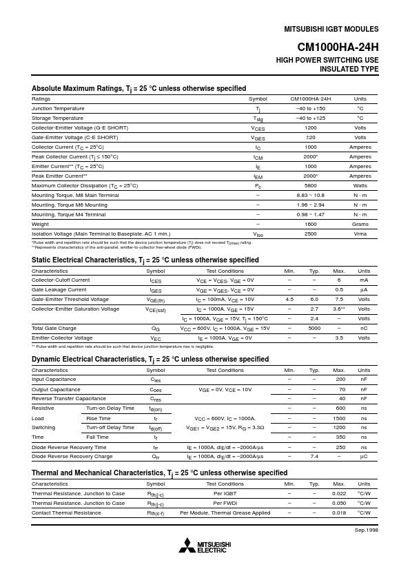
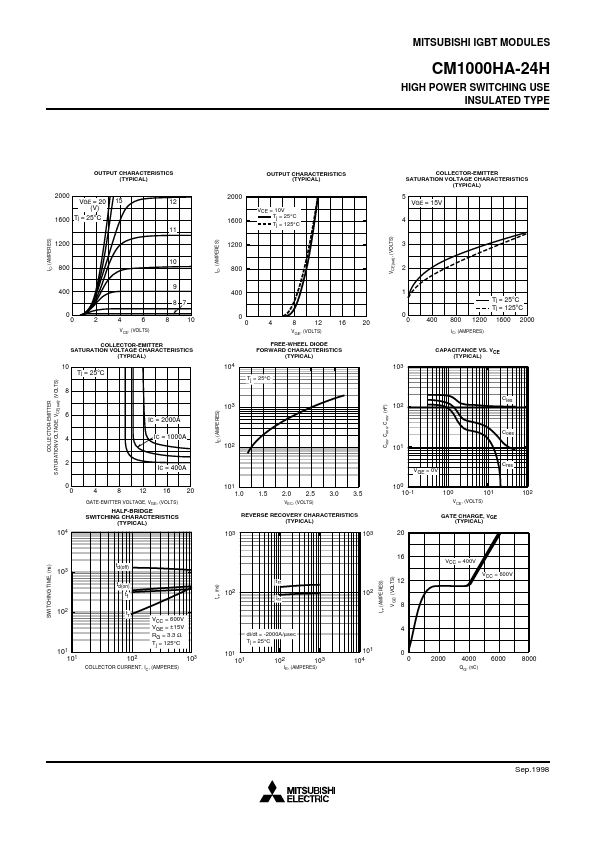
CM1000HA-24H Features
* ٗ Low Drive Power ٗ Low VCE(sat) ٗ Discrete Super-Fast Recovery Free-Wheel Diode ٗ High Frequency Operation ٗ Isolated Baseplate for Easy Heat Sinking Applications: ٗ AC Motor Control ٗ Motion/Servo Control ٗ UPS ٗ Welding Power Supplies Ordering Information: Example: Select the complete part modul
CM1000HA-24H_MitsubishiElectricSemiconductor.pdf
Datasheet Details
CM1000HA-24H
Mitsubishi Electric Semiconductor
49.55 KB
Igbt module.
CM1000HA-24H Distributor
📁 Related Datasheet
CM1000HA-24H IGBT Module (Powerex Power Semiconductors)
CM1000HA-28H IGBT Module (Mitsubishi Electric Semiconductor)
CM1000HA-28H IGBT Module (Powerex Power Semiconductors)
CM1000HA-34S IGBT Modules (Mitsubishi)
CM1000 HIGH CURRENT SILICON BRIDGE RECTIFIERS (Pan Jit International Inc.)
CM1000 HIGH CURRENT SILICON BRIDGE RECTIFIERS (TRSYS)
CM1000DU-34NF IGBT Module (Mitsubishi Electric)
CM1000DX-24T IGBT (Mitsubishi)