CM100DY-34A
Overview
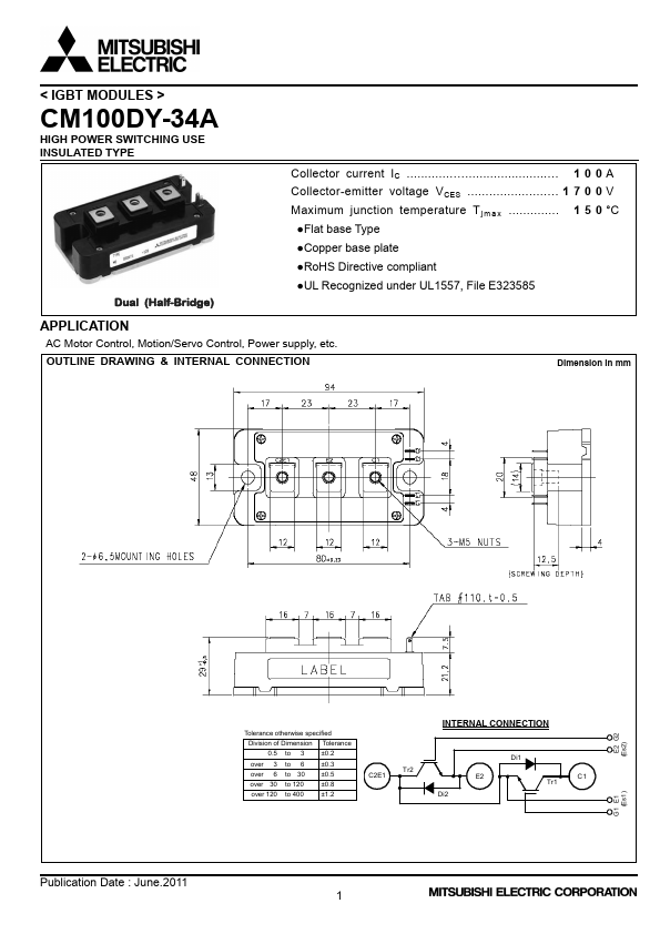
MITSUBISHI IGBT MODULES CM100DY-34A HIGH POWER SWITCHING USE CM100DY-34A ¡IC ................................................................... 100A ¡VCES ............................................
| Part | CM100DY-34A |
|---|---|
| Description | IGBT MODULES |
| Manufacturer | Mitsubishi Electric |
| Size | 429.87 KB |
MITSUBISHI IGBT MODULES CM100DY-34A HIGH POWER SWITCHING USE CM100DY-34A ¡IC ................................................................... 100A ¡VCES ............................................
| Part Number | Manufacturer | Description |
|---|---|---|
| NEO-6M | u-blox | 6 GPS Modules |
| ERL35 | FPE | POWER TRANSFORMER MODULES |
| VK2024 | VIKAY | Alphanumeric Dot Matrix Modules |