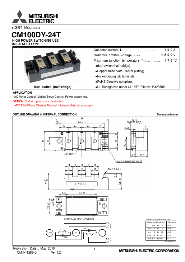
<IGBT Modules>
CM100DY-24T
HIGH POWER SWITCHING USE
INSULATED TYPE
MAXIMUM RATINGS (Tvj=25 °C, unless otherwise specified)
Symbol
Item
Conditions
VCES
Collector-emitter voltage
G-E short-circuited
VGES
IC
ICRM
Ptot
IE (Note1)
IERM (Note1)
Gate-emitter voltage
Collector current
Total power dissipation
Emitter current
C-E short-circuited
DC, TC=147 °C* (Note2, 4)
Pulse, Repetitive (Note3)
TC=25 °C (Note2, 4)
DC (Note2)
Pulse, Repetitive (Note3)
Visol
Tvjmax
TCmax
Tvjop
Tstg
Isolation voltage
Maximum junction temperature
Maximum case temperature
Operating junction temperature
Storage temperature
Terminals to base plate, RMS, f=60 Hz, AC 1 min
Instantaneous event (overload)
(Note4)
Continuous operation (under switching)
-
ELECTRICAL CHARACTERISTICS (T vj =25 °C, unless otherwise specified)
Symbol
Item
Conditions
ICES Collector-emitter cut-off current VCE=VCES, G-E short-circuited
IGES Gate-emitter leakage current
VGE=VGES, C-E short-circuited
VGE(th)
Gate-emitter threshold voltage
IC=10 mA, VCE=10 V
VCEsat
(Terminal)
VCEsat
(Chip)
Collector-emitter saturation voltage
IC=100 A, VGE=15 V,
Refer to the figure of test circuit
(Note5)
IC=100 A,
VGE=15 V,
(Note5)
T v j =25 °C
T v j =125 °C
T v j =150 °C
T v j =25 °C
T v j =125 °C
T v j =150 °C
Cies
Input capacitance
Coes
Output capacitance
VCE=10 V, G-E short-circuited
Cres
Reverse transfer capacitance
QG Gate charge
VCC=600 V, IC=100 A, VGE=15 V
td(on)
tr
Turn-on delay time
Rise time
VCC=600 V, IC=100 A, VGE=±15 V,
td(off)
tf
Turn-off delay time
Fall time
RG=3.9 Ω, Inductive load
V (Note.1)
EC
(Terminal)
V (Note.1)
EC
(Chip)
Emitter-collector voltage
IE=100 A, G-E short-circuited,
Refer to the figure of test circuit
(Note5)
IE=100 A,
G-E short-circuited,
(Note5)
T v j =25 °C
T v j =125 °C
T v j =150 °C
T v j =25 °C
T v j =125 °C
T v j =150 °C
t (Note1)
rr
Q (Note1)
rr
Reverse recovery time
Reverse recovery charge
VCC=600 V, IE=100 A, VGE=±15 V,
RG=3.9 Ω, Inductive load
Eon Turn-on switching energy per pulse VCC=600 V, IC=IE=100 A,
Eoff Turn-off switching energy per pulse VGE=±15 V, RG=3.9 Ω, T v j =150 °C,
E (Note1)
rr
Reverse recovery energy per pulse
Inductive load
RCC'+EE' Internal lead resistance
Main terminals-chip, per switch, TC=25 °C (Note4)
r g Internal gate resistance
Per switch
*: The value of PC-TIM applied module is limited by the heat resistant temperature of PC-TIM.
Min.
-
-
5.4
-
-
-
-
-
-
-
-
-
-
-
-
-
-
-
-
-
-
-
-
-
-
-
-
-
-
-
Rating
1200
± 20
100
200
1180
100
200
4000
175
150*
-40 ~ +150
-40 ~ +150*
Limits
Typ.
-
-
6.0
1.65
1.85
1.90
1.55
1.75
1.80
-
-
-
0.7
-
-
-
-
1.70
1.85
1.85
1.65
1.65
1.65
-
10
5.5
11.2
7.9
0.2
0
Max.
1.0
0.5
6.6
1.95
-
-
1.80
-
-
22.8
0.8
0.3
-
300
150
500
300
2.10
-
-
2.00
-
-
400
-
-
-
-
-
-
Unit
V
V
A
W
A
V
°C
°C
Unit
mA
μA
V
V
V
nF
μC
ns
V
V
ns
μC
mJ
mJ
mΩ
Ω
Publication Date : May 2018
CMH-11286-B
Ver.1.2
2