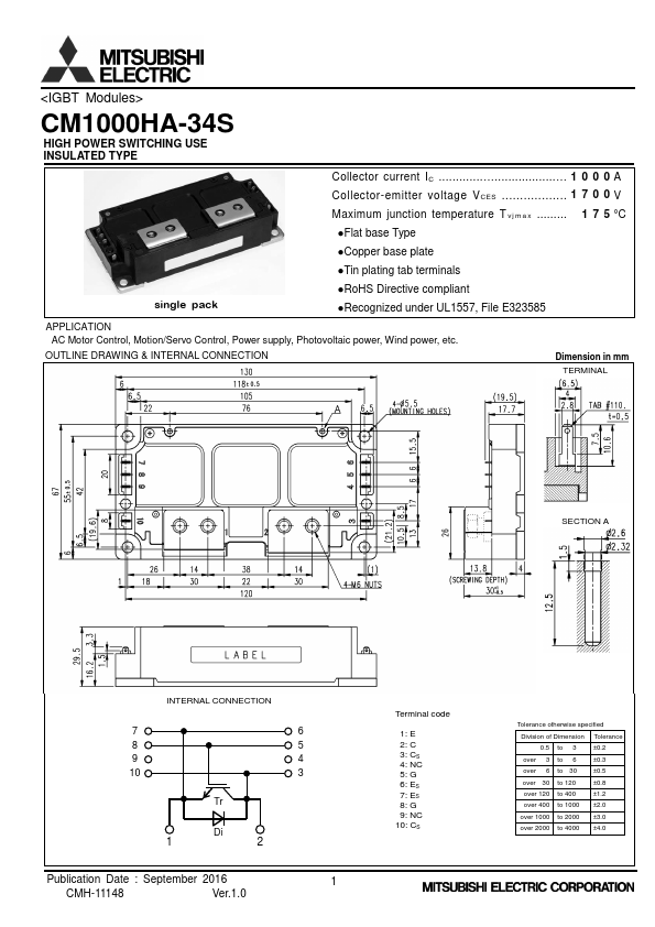
<IGBT Modules>
CM1000HA-34S
HIGH POWER SWITCHING USE
INSULATED TYPE
MAXIMUM RATINGS (Tvj=25 °C, unless otherwise specified)
Symbol
Item
Conditions
VCES
Collector-emitter voltage
G-E short-circuited
VGES
Gate-emitter voltage
C-E short-circuited
IC Collector current
ICRM
DC, TC=111 °C (Note2, 4)
Pulse, Repetitive (Note3)
Pt ot Total power dissipation
TC=25 °C (Note2, 4)
IE (Note1)
IERM (Note1)
Emitter current
DC (Note2)
Pulse, Repetitive (Note3)
Visol
Isolation voltage
Terminals to base plate, RMS, f=60 Hz, AC 1 min
Tvjmax
TCmax
Maximum junction temperature
Maximum case temperature
Instantaneous event (overload)
(Note4)
Tvjop
Operating junction temperature
Continuous operation (under switching)
T s t g Storage temperature
-
ELECTRICAL CHARACTERISTICS (Tvj=25 °C, unless otherwise specified)
Symbol
Item
Conditions
ICES
IGES
VGE(th)
Collector-emitter cut-off current
Gate-emitter leakage current
Gate-emitter threshold voltage
VCEsat
(Terminal)
VCEsat
(Chip)
Collector-emitter saturation voltage
Cies
Coes
Cres
QG
td(on)
tr
td(off)
tf
Input capacitance
Output capacitance
Reverse transfer capacitance
Gate charge
Turn-on delay time
Rise time
Turn-off delay time
Fall time
V (Note.1)
EC
(Terminal)
V (Note.1)
EC
(Chip)
Emitter-collector voltage
t (Note1)
rr
Q (Note1)
rr
Eon
Eoff
E (Note1)
rr
RCC'+EE'
rg
Reverse recovery time
Reverse recovery charge
Turn-on switching energy per pulse
Turn-off switching energy per pulse
Reverse recovery energy per pulse
Internal lead resistance
Internal gate resistance
VCE=VCES, G-E short-circuited
VGE=VGES, C-E short-circuited
IC=100 mA, VCE=10 V
IC=1000 A, VGE=15 V,
Refer to the figure of test circuit
(Note5)
IC=1000 A,
VGE=15 V,
(Note5)
T v j =25 °C
T v j =125 °C
T v j =150 °C
T v j =25 °C
T v j =125 °C
T v j =150 °C
VCE=10 V, G-E short-circuited
VCC=1000 V, IC=1000 A, VGE=15 V
VCC=1000 V, IC=1000 A, VGE=±15 V,
RG=0 Ω, Inductive load
IE=1000 A, G-E short-circuited,
Refer to the figure of test circuit
(Note5)
IE=1000 A,
G-E short-circuited,
(Note5)
VCC=1000 V, IE=1000 A, VGE=±15 V,
RG=0 Ω, Inductive load
VCC=1000 V, IC=IE=1000 A,
VGE=±15 V, RG=0 Ω, T v j =150 °C,
Inductive load
Main terminals-chip, TC=25 °C (Note4)
-
T v j =25 °C
T v j =125 °C
T v j =150 °C
T v j =25 °C
T v j =125 °C
T v j =150 °C
Min.
-
-
5.4
-
-
-
-
-
-
-
-
-
-
-
-
-
-
-
-
-
-
-
-
-
-
-
-
-
-
-
Rating
1700
± 20
1000
2000
7140
1000
2000
4000
175
125
-40 ~ +150
-40 ~ +125
Limits
Typ.
-
-
6.0
2.10
2.35
2.45
2.00
2.25
2.35
-
-
-
4.2
-
-
-
-
2.10
2.20
2.15
2.00
2.10
2.05
-
200
589
253
245
0.2
2.2
Max.
1.0
0.5
6.6
2.60
-
-
2.50
-
-
230
24
4.0
-
900
300
900
400
2.60
-
-
2.50
-
-
500
-
-
-
-
-
-
Unit
V
V
A
W
A
V
°C
°C
Unit
mA
μA
V
V
V
nF
μC
ns
V
V
ns
μC
mJ
mJ
mΩ
Ω
Publication Date : September 2016
CMH-11148
Ver.1.0
2