Datasheet Details
| Part number | CL88031 |
|---|---|
| Manufacturer | Microchip |
| File Size | 574.23 KB |
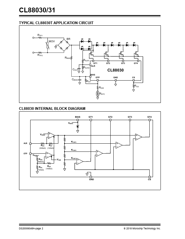
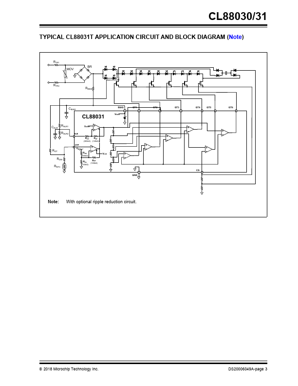
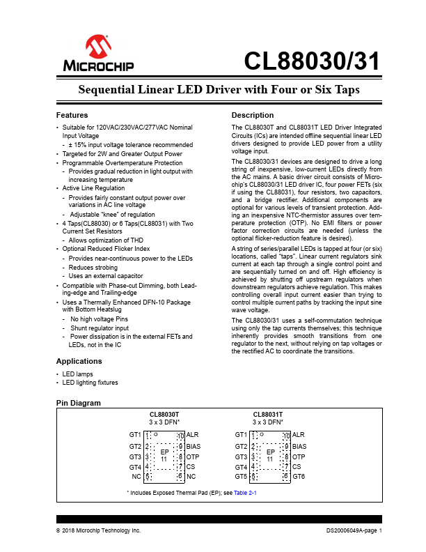
| Description | Sequential Linear LED Driver |
| Datasheet |
 CL88031 Datasheet CL88031 Datasheet
|
|
|
Download the CL88031 datasheet PDF. This datasheet also covers the CL88030 variant, as both devices belong to the same sequential linear led driver family and are provided as variant models within a single manufacturer datasheet.
| Part number | CL88031 |
|---|---|
| Manufacturer | Microchip |
| File Size | 574.23 KB |
| Description | Sequential Linear LED Driver |
| Datasheet |
CL88031 Datasheet
|
|
|
|
| Part Number | Description | Manufacturer |
|---|---|---|
| CL8800 | Sequential Linear LED Driver | Supertex |
| CL8800K63-G | Sequential Linear LED Driver | Supertex |
| CL8801 | Sequential Linear LED Driver | Supertex |
| CL8801K63-G | Sequential Linear LED Driver | Supertex |
| CL8805 | DC/DC Boost Converter | ChipSourceTek |
| Part Number | Description |
|---|---|
| CL88030 | Sequential Linear LED Driver |
| CL8800 | Sequential Linear LED Driver |
| CL8801 | Sequential Linear LED Driver |
The following content is an automatically extracted verbatim text from the original manufacturer datasheet and is provided for reference purposes only.