$6$6
9ROWDJH5DQJHWR9
)RUZDUG&XUUHQW $PSHUH
$;,$/6,/$67,&*8$5'-81&7,2167$1'$5'5(&7,),(5
FEATURES
▪ Low coVt construction
▪ Low forward voltage
▪ High forward surge current capability
▪ High temperature soldering guaranteed:
260/10 secods.0.375”(9.5mm)lead length
1.0(25.4)
MIN.
R-6S
0 0 52(1.3)
0 0 48(1.2)
DIA.
MECHANICAL DATA
▪ Case: Transfer molded plastic
▪ Epoxy: UL94V-O rate flame retardant
▪ Polarity: Color band denotes cathode end
▪ Lead: Plated axial lead, solderable per MIL-STD-202E method 208C
▪ Mounting position: Any
▪ Weight: 0.06ounce, 1.7 grams
0.360(9.1)
0.340(8 6)
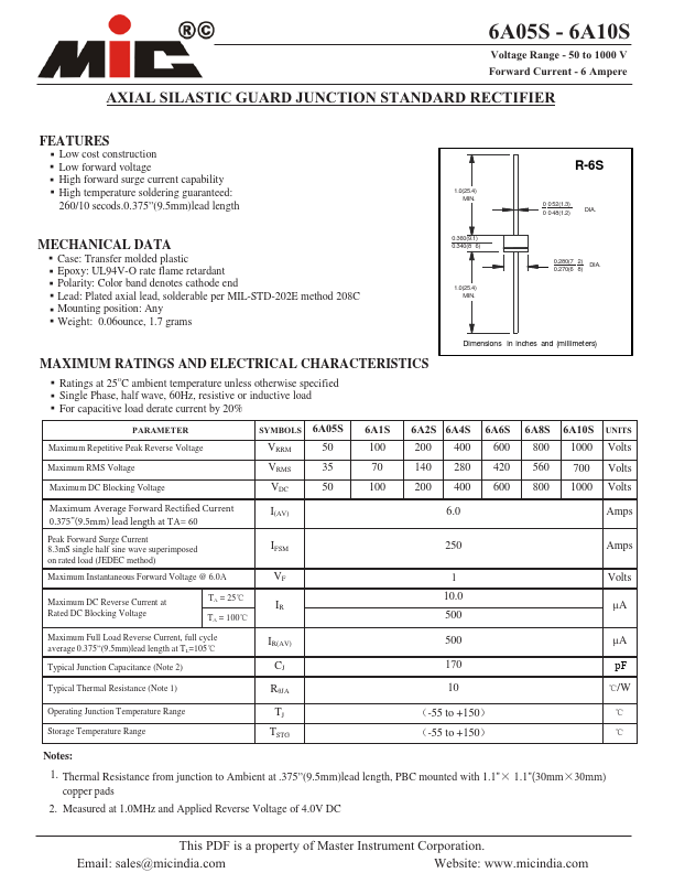
1.0(25.4)
MIN.
0.280(7 2) DIA.
0.270(6 8)
Dimensions in inches and (millimeters)
MAXIMUM RATINGS AND ELECTRICAL CHARACTERISTICS
▪ Ratings at 25OC ambient temperature unless otherwise specified
▪ Single Phase, half wave, 60Hz, resistive or inductive load
▪ For capacitive load derate current by 20%
3$5$0(7(5
Maximum Repetitive Peak Reverse Voltage
Maximum RMS Voltage
Maximum DC Blocking Voltage
6<0%2/6 $6
VRRM
50
VRMS
35
VDC 50
$6
100
70
100
$6 $6 $6 $6 $6 81,76
200 400 600 800 1000 Volts
140 280 420 560 700 Volts
200 400 600 800 1000 Volts
.BYJNVN"WFSBHF'PSXBSE3FDUJGJFE$VSSFOU
w NN
MFBEMFOHUIBU5"
Peak Forward Surge Current
8.3mS single half sine wave superimposed
on rated load (JEDEC method)
Maximum Instantaneous Forward Voltage @ 6.0A
Maximum DC Reverse Current at
Rated DC Blocking Voltage
TA = 25
TA = 100
I(AV)
IFSM
VF
IR
6.0 Amps
250 Amps
Volts
10.0
µA
500
Maximum Full Load Reverse Current, full cycle
average 0.375”(9.5mm)lead length at TL=105
Typical Junction Capacitance (Note 2)
IR(AV)
CJ
500 µA
10 pF
Typical Thermal Resistance (Note 1)
RθJA
10
/W
Operating Junction Temperature Range
Storage Temperature Range
TJ
TSTG
-55 to +150
-55 to +150
Notes:
1. Thermal Resistance from junction to Ambient at .375”(9.5mm)lead length, PBC mounted with 1.1”
DPQQFSQBET
2. Measured at 1.0MHz and Applied Reverse Voltage of 4.0V DC
1.1”(30mm NN
7KLV3')LVDSURSHUW\RI0DVWHU,QVWUXPHQW&RUSRUDWLRQ
(PDLOVDOHV#PLFLQGLDFRP
:HEVLWHZZZPLFLQGLDFRP