SMBJ64C
SMBJ64C is 600Watt TVS manufactured by Micro Commercial Components.
- Part of the SMBJ5.0 comparator family.
- Part of the SMBJ5.0 comparator family.
Features
- For Surface Mount Applicationsin Order to Optimize Board Space
- Low Inductance
- Fast Response Time: Typical Less than 1ps From 0V to VBR min
- Halogen Free. “Green” Device (Note 1)
- Moisture Sensitivity Level 1
- Epoxy Meets UL 94 V-0 Flammability Rating
- Lead Free Finish/Ro HS pliant (Note 2) ("P" Suffix Designates Ro HS pliant. See Ordering Information)
- For Bidirectional Devices Add “C” To The Suffix of The Part Number: i.e.SMBJ5.0CA for 5% Tolerance
Mechanical Data
- Polarity: Color Band Denotes Positive end( cathode) Except Bi-directional Types
- Maximum Soldering Temperature:260°C for 10 Seconds
- Terminals: Solderable Per MIL-STD-750, Method 2026
Maximum Ratings
- Operating Junction Temperature Range: -55°C to +175°C
- Storage Temperature Range: -55°C to +175°C
- Thermal Resistance :20°C/W Junction to Lead
- Thermal Resistance :25°C/W Junction to Case
- Thermal Resistance :100°C/W Junction to Ambient
Electrical Characteristics @ 25°C Unless Otherwise Specified
Peak Pulse Power
Surge Current on
10/1000μs Waveform
See the Table
Note 3
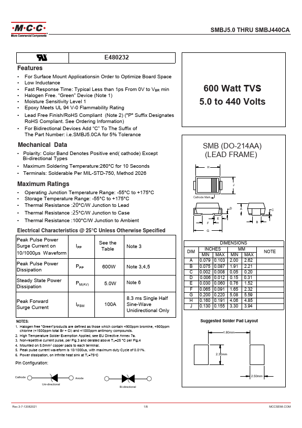
Peak Pulse Power Dissipation
600W Note 3,4,5
Steady State Power Dissipation
PM(AV)
5.0W Note 6
Peak Forward Surge Current
8.3 ms Single Half
IFSM
100A Sine-Wave
Unidirectional Only
NOTES: 1. Halogen free "Green"products are defined as those which contain <900ppm bromine, <900ppm chlorine (<1500ppm total Br + Cl) and <1000ppm antimony pounds. 2. High Temperature Solder Exemption Applied, see EU Directive Annex 7a. 3. Non-repetitive current pulse, per Fig.3 and derated above TA=25 °C per Fig.4 4. Mounted on 5.0mm2 copper pads to each terminal. 5. Peak pulse current waveform is 10/1000us, with maximum duty Cycle of 0.01%. 6. Power dissipation, on infinite heat sink at TL=75o C
Pin Configuration:
Cathode...