1N4148WL Overview
Key Specifications
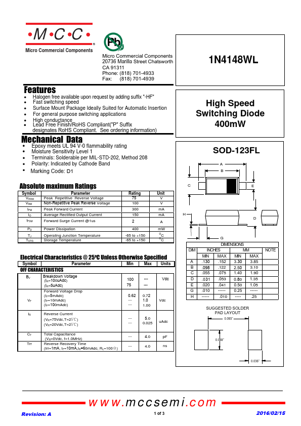
Mount Type: Surface Mount
Pins: 2
Max Operating Temp: 150 °C
Min Operating Temp: -65 °C
Key Features
- Halogen free available upon request by adding suffix "-HF"
- Fast switching speed
- Surface Mount Package Ideally Suited for Automatic Insertion
- For general purpose switching applications
- High conductance
- Lead Free Finish/RoHS Compliant("P" Suffix designates RoHS Compliant. See Mechanical Data
- Epoxy meets UL 94 V-0 flammability rating
- Moisture Sensitivity Level 1
- Terminals: Solderable per MIL-STD-202, Method 208
- Polarity: Indicated by Cathode Band