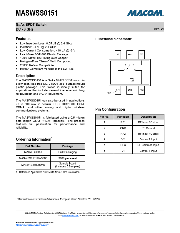
MASWSS0151
GaAs SPDT Switch
DC - 3 GHz
Electrical Specifications2: TA = 25°C, VC = 0 V / -3 V, PIN = 0 dBm, Z0 = 50 Ω
Parameter
Test Conditions
Units Min.
Typ.
Insertion Loss
Isolation
Return Loss
P1dB
DC - 3.0 GHz
DC - 1.0 GHz
1.0 - 2.0 GHz
2.0 - 3.0 GHz
DC - 1.5 GHz
1.5 - 3.0 GHz
1 GHz
dB
dB
dB
dBm
—
29
—
—
—
—
0.65
31
25
21
22
20
31
IP2
2 Tone, 10 dBm / Tone, 900 MHz, 5 MHz Spacing dBm
—
81
IP3
2 Tone, 10 dBm / Tone, 900 MHz, 5 MHz Spacing dBm
—
55
2nd Harmonic
2.4 GHz, PIN = 20 dBm
dBc —
-70
3rd Harmonic
2.4 GHz, PIN = 20 dBm
dBc —
-60
TON, TOFF
50% control to 90% RF, 50% control to 10% RF ns
—
20
TRISE, TFALL
10% to 90% RF, 90% to 10% RF
ns —
10
Control Current
—
µA —
5
2. For positive voltage control, external DC blocking capacitors are required on all RF ports.
Rev. V6
Max.
0.8
—
—
—
—
—
—
—
—
—
10
Absolute Maximum Ratings3,4
Parameter
Absolute Maximum
Input Power (1 GHz)
32 dBm
Operating Voltage
8 Volts
Operating Temperature
-40°C to +85°C
Storage Temperature
-65°C to +150°C
3. Exceeding any one or combination of these limits may cause
permanent damage to this device.
4. MACOM does not recommend sustained operation near these
survivability limits.
Truth Table 5,6
V1
V2
RFC-RF1
RFC-RF2
10
Off
On
01
On
Off
5. Differential voltage, V (state 1) - V (state 0), must be +2.1 V
minimum and must not exceed 5 V.
6. 0 = -5 V to 0 V, 1 = -2.9 V to 5 V.
Handling Procedures
Please observe the following precautions to avoid
damage:
Static Sensitivity
Gallium Arsenide Integrated Circuits are sensitive
to electrostatic discharge (ESD) and can be
damaged by static electricity. Proper ESD control
techniques should be used when handling these
devices.
2
M/A-COM Technology Solutions Inc. (MACOM) and its affiliates reserve the right to make changes to the product(s) or information contained herein without notice.
Visit www.macom.com for additional data sheets and product information.
For further information and support please visit:
https://www.macom.com/support