IRS20954SPBF Overview
Key Specifications
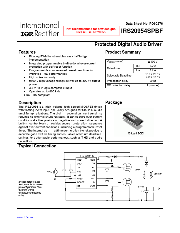
Package: SOP
Mount Type: Surface Mount
Pins: 16
Max Voltage (typical range): 18 V
Description
The IRS2 0954 is a high voltage, high spe ed M OSFET drive r with floating PWM input, spe cially desi gned for Cla ss D au dio amplifier ap plications. The bi-di rectional cu rrent sensi ng requires no external shunt resistors.
Key Features
- Floating PWM input enables easy half bridge implementation
- Integrated programmable bi-directional over-current protection with self-reset function
- Programmable compensated preset deadtime for improved THD performances
- High noise immunity
- ±100 V high voltage ratings deliver up to 500 W output power