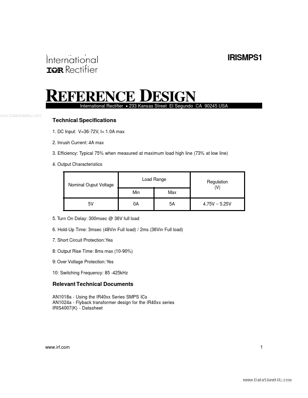
Download IRISMPS1 Datasheet PDF
International Rectifier
IRISMPS1
IRISMPS1 is REFERENCE DESIGN manufactured by International Rectifier.
Description The IRISMPS2 refererence design is a plete tested power supply circuit. It is designed for a 36-72V DC line input and will provide a 5V, 5A full load DC output. The design uses a flyback converter topology, with an IRIS4007K as the main switch and control device. The initial startup current for the IRIS4007K is provided by a dropper resistor from the DC bus. Once the circuit is started the Vcc power for the IRIS4007K es from the bias winding of the main transformer. The primary .. current control circuit consists of a current sensing resistor which feeds a voltage proportional to the transformer primary current into the feedback (FB) pin of the IRIS4007K. The secondary voltage control loop uses a zener diode as the reference and an optocoupler to feedback the information across the transformer isolation boundary back to the control circuit of the IRIS4007K. Test Circuit Set-up The circuit is designed for a 36-72V DC line input. To effectively test and evaluate this circuit it ios remended that a DC power supply with a 100V range is used that is capable of supplying 5A. The DC input power is applied to the pins at P1(+) and P4(gnd) marked on the board. For the output the best load to use is an electronic load which will allow easy changes in the output load, e.g. something like a Chroma 63102. Another simple alternative is to use a High power resistor for the load. Circuit Operation The front end of the circuit consists of an EMI Filter. At power up the DC voltage is applied to the top of the transformer, and the top of resistor R3. R3 allows about 450u A of quiescent current to flow which charges the Vcc capacitor C9. When the voltage at the Vcc pin of the IRIS4007K reaches the positive undervoltage lockout threshold (VCCUV+) , the IRIS4007K starts to operate and will turn on the internal FET. Now the DC bus voltage is applied across the transformer primary winding, the FET and the current sense resistor R10. The current through the transformer...