The following content is an automatically extracted verbatim text
from the original manufacturer datasheet and is provided for reference purposes only.
View original datasheet text
www.DataSheet4U.com
PD- 95917
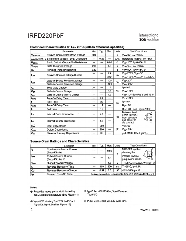
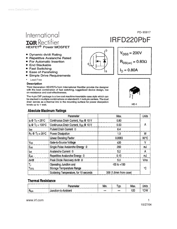
IRFD220PbF
Lead-Free
www.irf.com
1
10/27/04
IRFD220PbF
2
www.irf.com
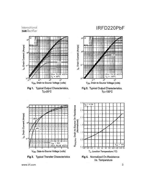
IRFD220PbF
www.irf.com
3
IRFD220PbF
4
www.irf.com
IRFD220PbF
www.irf.com
5
IRFD220PbF
6
www.irf.com
IRFD220PbF
Peak Diode Recovery dv/dt Test Circuit
+
Circuit Layout Considerations • Low Stray Inductance • Ground Plane • Low Leakage Inductance Current Transformer
+ +
-
• dv/dt controlled by RG • ISD controlled by Duty Factor "D" • D.U.T. - Device Under Test
+ -
*
Reverse Polarity for P-Channel ** Use P-Channel Driver for P-Channel Measurements
Driver Gate Drive P.W. Period D=
P.W. Period VGS=10V
D.U.T. ISD Waveform Reverse Recovery Current Body Diode Forward Current di/dt D.U.T.
 IRFD220PBF Datasheet