Datasheet4U Logo Datasheet4U.com

IRF3704ZCS - Power MOSFET

Download the IRF3704ZCS datasheet PDF. This datasheet also covers the IRF3704ZCL variant, as both devices belong to the same power mosfet family and are provided as variant models within a single manufacturer datasheet.
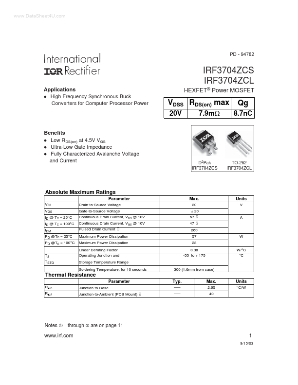
Features

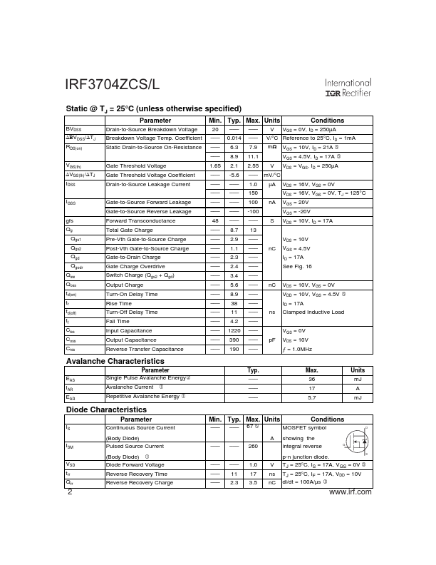
  • -source charge into two sub elements, Qgs1 and Qgs2, can be seen from Fig 16. Qgs2 indicates the charge that must be supplied by the gate driver between the time that the threshold voltage has been reached and the time the drain current rises to Idmax at which time the drain voltage begins to change. Minimizing Qgs2 is a critical factor in reducing switching losses in Q1. Qoss is the charge that must be supplied to the output capacitance of the MOSFET during every switching cycle. Figure A shows.

📥 Download Datasheet

Note: The manufacturer provides a single datasheet file (IRF3704ZCL_InternationalRectifier.pdf) that lists specifications for multiple related part numbers.

Full PDF Text Transcription (Reference)

The following content is an automatically extracted verbatim text from the original manufacturer datasheet and is provided for reference purposes only.

View original datasheet text
www.DataSheet4U.com PD - 94782 IRF3704ZCS IRF3704ZCL Applications l High Frequency Synchronous Buck Converters for Computer Processor Power HEXFET® Power MOSFET VDSS RDS(on) max 20V 7.9m: Qg 8.7nC Benefits l Low RDS(on) at 4.5V VGS l Ultra-Low Gate Impedance l Fully Characterized Avalanche Voltage and Current D2Pak IRF3704ZCS TO-262 IRF3704ZCL Absolute Maximum Ratings Parameter VDS VGS ID @ TC = 25°C ID @ TC = 100°C IDM PD @TC = 25°C PD @TC = 100°C TJ TSTG Drain-to-Source Voltage Gate-to-Source Voltage Continuous Drain Current, VGS @ 10V Continuous Drain Current, VGS @ 10V Pulsed Drain Current Max. 20 ± 20 67 47 Units V A c g g 260 57 28 0.
Published: |