Datasheet Summary
.. s mu @
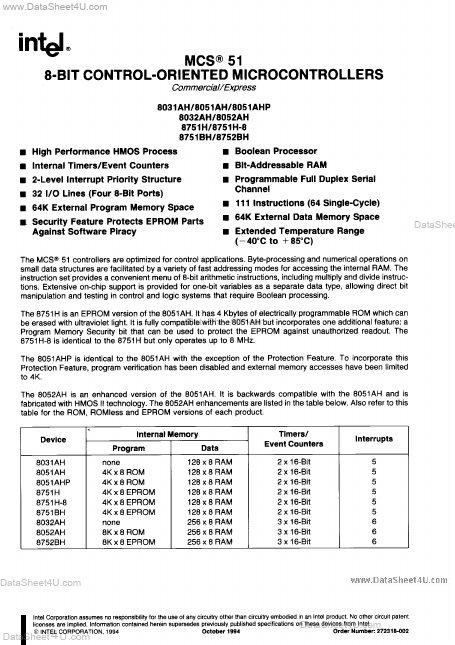
MCS@51 8-BIT CONTROL-ORIENTED MICROCONTROLLERS mercial/Express 8031AH18051AH18051AHP 8032N+18052N-I 8751W8751H-8 8751BW8752BI-I s High Performance HMOS Process s Internal Timers/Event Counters s 2-Level interrupt Priority Structure s 32 1/0 Lines (Four 8-Bit Ports) s 64K External Program Memory Space s Security Feature Protects EPROM Parts s Boolean Processor s Bit-Addressable RAM s Programmable Full Duplex Serial
Channel s 111 Instructions (64 Single-Cycle) s s Extended Temperature Range
64K External Data Memory Space (- 40”C to +85”C)
Against Software Piracy
DataShee
The MCS@51 controllers are optimized for control applications. Byte-processing and...