P15N100C
P15N100C is IXGP15N100C manufactured by IXYS.
Features
V V V V A A A A
G E C (TAB)
G CE
TO-220AB (IXGP)
TO-263 AA (IXGA)
Maximum lead temperature for soldering 1.6 mm (0.062 in.) from case for 10 s Md Weight Mounting torque with screw M3 Mounting torque with screw M3.5 TO-220 TO-263
0.45/4 Nm/lb.in. 0.55/5 Nm/lb.in. 4 2 g g
- International standard packages
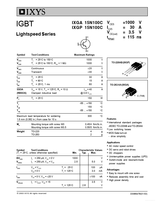
JEDEC TO-220AB and TO-263AA
- Low switching losses
- MOS Gate turn-on
- drive simplicity Applications
Symbol Test Conditions (TJ = 25°C, unless otherwise specified) BVCES VGE(th) ICES IC = 250 µA, VGE = 0 V IC = 250 µA, VCE = VGE VCE = VCES VGE = 0 V IGES VCE(sat) VCE = 0 V, VGE = ±20 V IC = ICE90, VGE = 15
Min. 1000 2.5 TJ = 25°C TJ = 125°C
Characteristic Values Typ. Max. V 5.0 100 3.0 ± 100 3.5 V µA m A n A V V
- AC motor speed control
- DC servo and robot drives
- DC choppers
- Uninterruptible power supplies (UPS)
- Switch-mode and resonant-mode power supplies
Advantages
- Easy to mount with one screw
- Reduces assembly time and cost
- High power density
TJ = 125°C
© 2003 IXYS All rights reserved
DS98647B(01/03)
Free Datasheet http://.datasheetlist./
IXGA 15N100C IXGP 15N100C
Symbol Test Conditions (TJ = 25°C, unless otherwise specified) gfs Cies Coes Cres Qg Qge Qgc td(on) tri td(off) tfi Eoff td(on) tri Eon td(off) tfi Eoff Rth JC Rth CK TO-220 0.5 Inductive load, TJ = 25°C IC = IC90, VGE = 15 V VCE = 960 V, RG = Roff = 10 Ω Remarks: Switching times may increase for VCE (Clamp) > 0.8 VCES, higher TJ or increased RG Inductive load, TJ = 125°C IC = IC90, VGE = 15 V VCE = 960 V, RG = Roff = 10 Ω Remarks: Switching times may increase for VCE (Clamp) > 0.8 VCES, higher TJ or increased RG IC = IC90, VGE = 15 V, VCE = 0.5 VCES VCE = 25 V, VGE = 0 V, f = 1 MHz IC = IC90; VCE = 10 V, Pulse test, t ≤ 300 µs, duty cycle ≤ 2 % 1720 95 35 73 13 26 25 15 150 101 0.85 25 18 0.60 220 210 1.85 0.83 200 160 1.40 p F p F p F n C n C n C ns ns ns ns m J ns ns m J ns ns m J K/W K/W TO-263 AA Outline
Pins: 1
- Gate 3
- Emitter 2
- Collector 4
- Collector Bottom...