Datasheet4U Logo Datasheet4U.com

C0044BG400 - IGBT Gate Driver

General Description

Start up behavior An un-powered gate driver applies impedance to the gate

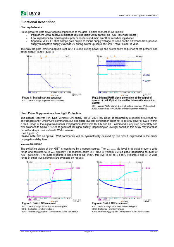
emitter connection as follows: - Permanent 20kΩ passive resistance (plus possible 20kΩ parallel on “IGBT Interface Board”) - Low impedance by discharged supply capacitors and main amplifier freewheeling diodes.

Key Features

  • High reliability topology.
  • Separate gate interface card for optimal packaging.
  • Designed for ultra low power consumption.
  • Balanced supply current in ON and OFF mode.
  • Build in DC/DC-converter with soft start.
  • Integrated input filter for low EMI.
  • Separate low impedance path for parasitic EMI currents.
  • PD-Voltage levels available up to 7kV.
  • Low impedance from gate to emitter at start-up and power fail.
  • Monitor.

📥 Download Datasheet

Full PDF Text Transcription (Reference)

The following content is an automatically extracted verbatim text from the original manufacturer datasheet and is provided for reference purposes only.

View original datasheet text
IGBT Gate Driver Type C0044BG400 Date: - 20th Dec 2019 Data Sheet Issue: - 4 IGBT Gate Driver Type C0044BG400 Special Features • High reliability topology • Separate gate interface card for optimal packaging • Designed for ultra low power consumption • Balanced supply current in ON and OFF mode • Build in DC/DC-converter with soft start • Integrated input filter for low EMI • Separate low impedance path for parasitic EMI currents • PD-Voltage levels available up to 7kV • Low impedance from gate to emitter at start-up and power fail • Monitoring of all secondary supply voltages • Monitoring of IGBT switching status (VCE-desat detection) • Soft switch-OFF at VCE-desat fault condition • Fibre-optic links for switching commands and status control • Low light protection for input signal • Sho