CM0402-56N
Key Features
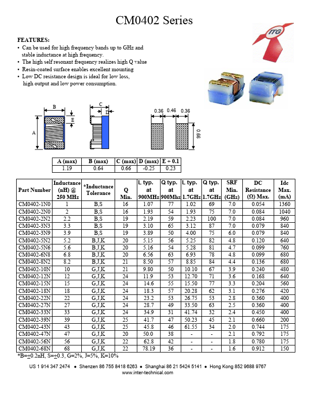
- Can be used for high frequency bands up to GHz and stable inductance at high frequency.
- The high self resonant frequency realizes high Q value
- Resin-coated surface enables excellent mounting
- Low DC resistance design is ideal for low loss, high output and low power consumption. B E C
- 0.36 0.46 0.36
- 66 A A (max) 1.19 B (max) 0.64 C (max) D (max) E + 0.1 0.66 -0.25 0.23 L typ. Q typ. L typ. Q typ. SRF at at at at Min. 900MHz 900Mhz 1.7GHz 1.7GHz (GHz) 1.07 77 1.02 69 7.0 1.93 54 1.93 75 7.0 2.19 59 2.23 100 7.0 3.10 65 3.12 87 7.0 3.89 50 4.00 75 6.0 5.15 56 5.25 82 4.8 5.16 54 5.28 81 4.7 6.56 63 6.93 78 4.8 8.50 57 8.85 84 4.4 9.80 50 10.10 67 3.9 11.9 53 12.70 71 3.6 14.6 55 15.50 77 3.3 18.3 57 20.28 62 3.1 23.2 53 26.75 53 2.8 28.7 49 33.50 63 2.5 34.9 31 41.74 32 2.4 41.7 47 50.23 45 2.1 45.8 46 61.55 34 2.0 50.0 38 2.1 62.8 42 1.8 78.19 36 1.6 DC Resistance (Ω) Max. 0.054 0.084 0.084 0.079 0.079 0.120 0.099 0.099 0.136 0.240 0.168 0.204 0.276 0.360 0.360 0.450 0.660 0.744 0.792 0.780 0.912 Idc Max. (mA) 1360 1040 960 840 840 640 760 680 680 480 640 560 420 400 400 400 200 175 175 175 150 Inductance *Inductance Part Number (nH) @ Tolerance 250 MHz CM0402-1N0 1 B,S CM0402-2N0 2 B,S CM0402-2N2 2.2 B,S CM0402-3N3 3.3 B,S CM0402-3N9 3.9 B,S CM0402-5N2 5.2 B,J,K CM0402-5N6 5.6 B,J,K CM0402-6N8 6.8 B,J,K CM0402-8N2 8.2 B,J,K CM0402-10N 10 G,J,K CM0402-12N 12 G,J,K CM0402-15N 15 G,J,K CM0402-18N 18 G,J,K CM0402-22N 22 G,J,K CM0402-27N 27 G,J,K CM0402-33N 33 G,J,K CM0402-39N 39 G,J,K CM0402-43N 43 G,J,K CM0402-47N 47 G,J,K CM0402-56N 56 G,J,K CM0402-68N 68 G,J,K *B=+0.2nH, S=+0.3, G=2%, J=5%, K=10% Q Min. 16 16 19 19 19 20 20 20 21 21 24 24 24 24 24 24 25 25 20 22 22