Datasheet Details
| Part number | IMP525 |
|---|---|
| Manufacturer | IMP Inc |
| File Size | 191.01 KB |
| Description | SINGLE CELL BATTERY POWERED ELECTROLUMINESCENT LAMP DRIVER/INVERTER |
| Datasheet |
 IMP525 Datasheet IMP525 Datasheet
|
|
|
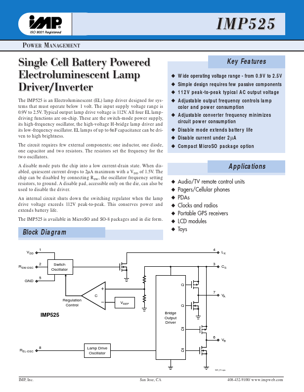
Positive voltage supply for the IMP525.
Inductor L may be connected here or to a separate supply.
Switch-mode resistor pin.
| Part number | IMP525 |
|---|---|
| Manufacturer | IMP Inc |
| File Size | 191.01 KB |
| Description | SINGLE CELL BATTERY POWERED ELECTROLUMINESCENT LAMP DRIVER/INVERTER |
| Datasheet |
IMP525 Datasheet
|
|
|
|
| Part Number | Description | Manufacturer |
|---|---|---|
| IMP5218 | Pllug and Pllay SCSII Termiinattor | IMP |
| IMP5219 | SCSII Termiinattor | IMP |
| IMP5225 | 18-Line Plug and Play SCSI Terminator | IMP |
| IMP5226 | 18-Line Plug and Play SCSI Terminator | IMP |
| IMP5111 | 9-Line SCSI Terminator | IMP |
| Part Number | Description |
|---|---|
| IMP522 | Dual EL Lamp Driver |
| IMP527 | SINGLE CELL BATTERY POWERED ELECTROLUMINESCENT LAMP DRIVER/INVERTER |
| IMP528 | HIGH-VOLTAGE EL LAMP DRIVER |
| IMP560 | POWER EFFICIENT EL LAMP DRIVER |
| IMP1232 | 5V P Power Suppl er Supply Monit y Monitor and or and Reset Cir eset Circuit |
The following content is an automatically extracted verbatim text from the original manufacturer datasheet and is provided for reference purposes only.