SA8.0
SA8.0 is TRANSZORB TRANSIENT VOLTAGE SUPPRESSOR manufactured by General Semiconductor.
FEATURES
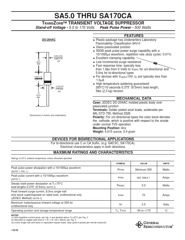
0.034 (0.86) 1.0 (25.4) MIN. 0.028 (0.71) DIA.
0.300 (7.6) 0.230 (5.8)
0.140 (3.6) 0.104 (2.6) DIA. 1.0 (25.4) MIN.
- Plastic package has Underwriters Laboratory Flammability Classification 94V-0
- Glass passivated junction
- 500W peak pulse power surge capability with a 10/1000µs waveform, repetition rate (duty cycle): 0.01%
- Excellent clamping capability
- Low incremental surge resistance
- Fast response time: typically less than 1.0ps from 0 Volts to V(BR) for uni-directional and 5.0ns for bi-directional types
- For devices with V(BR)≥10V, ID are typically less than 1.0µA
- High temperature soldering guaranteed: 265°C/10 seconds 0.375” (9.5mm) lead length, 5lbs (2.3 kg) tension
MECHANICAL DATA
Case: JEDEC DO-204AC molded plastic body over passivated junction Terminals: Solder plated axial leads, solderable per MIL-STD-750, Method 2026 Polarity: For uni-directional types the color band denotes the cathode, which is positive with respect to the anode under normal TVS operation Mounting Position: Any Weight: 0.015 ounce, 0.4 gram
Dimensions in inches and (millimeters)
DEVICES FOR BIDIRECTIONAL APPLICATIONS
For bi-directional use C or CA Suffix. (e.g. SA5.0C, SA170CA). Electrical characteristics apply in both directions.
MAXIMUM RATINGS AND CHARACTERISTICS
Ratings at 25°C ambient temperature unless otherwise specified
SYMBOL
VALUE
UNITS
Peak pulse power dissipation with a 10/1000µs waveform
(NOTE 1, FIG. 1)
PPPM IPPM PM(AV)
Minimum 500
SEE TABLE 1
Watts Amps Watts
Peak pulse current with a 10/1000µs waveform
(NOTE 1)
Steady state power dissipation at TL=75°C lead lengths 0.375" (9.5mm) (NOTE 2) Peak forward surge current, 8.3ms single half sine-wave superimposed on rated load, unidirectional only (JEDEC Method) (NOTE 3) Maximum instantaneous forward voltage at 35A for unidirectional only Operating junction and storage temperature range
NOTES (1) Non-repetitive current pulse, per Fig. 3 and derated above TA=25°C per Fig. 2 (2) Mounted on...