Datasheet Details
| Part number | SL13-S |
|---|---|
| Manufacturer | Formosa MS |
| File Size | 53.55 KB |
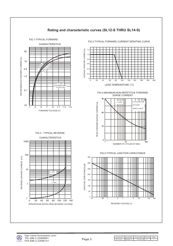
| Description | Chip Rectifier Low VF Schottky Barrier |
| Datasheet |
 SL13-S Datasheet SL13-S Datasheet
|

|
|
Download the SL13-S datasheet PDF. This datasheet also covers the SL12-S variant, as both devices belong to the same chip rectifier low vf schottky barrier family and are provided as variant models within a single manufacturer datasheet.
| Part number | SL13-S |
|---|---|
| Manufacturer | Formosa MS |
| File Size | 53.55 KB |
| Description | Chip Rectifier Low VF Schottky Barrier |
| Datasheet |
SL13-S Datasheet
|
|
|
|
| Part Number | Description | Manufacturer |
|---|---|---|
| SL13-S | 1A SMD LOW VF SCHOTTKY BARRIER RECTIFIERS | Frontier Electronics |
| SL13 | 1.0A LOW VF SURFACE MOUNT SCHOTTKY BARRIER RECTIFIER | WON-TOP |
| SL13 | LOW VF SURFACE MOUNT SCHOTTKY BARRIER RECTIFIER(VOLTAGE - 20 to 40 Volts CURRENT - 1.0 Ampere) | Pan Jit International Inc. |
| SL13 | LOW VF SURFACE MOUNT SCHOTTKY BARRIER RECTIFIER | YS |
| SL13 | Surface Mount Schottky Rectifier | Vishay |
| Part Number | Description |
|---|---|
| SL12 | Low VF Chip Schottky Barrier Diodes |
| SL12-M | Low VF Chip Schottky Barrier Diodes |
| SL12-S | Chip Rectifier Low VF Schottky Barrier |
| SL14 | Low VF Chip Schottky Barrier Diodes |
| SL14-M | Low VF Chip Schottky Barrier Diodes |
The following content is an automatically extracted verbatim text from the original manufacturer datasheet and is provided for reference purposes only.