KLFM130-HST Overview
Chip Low Leakage Schottky Barrier Rectifier Formosa MS KLFM120-HST THRU KLFM140-HST List List................................................................................................. 1 Package outline...............................................................................
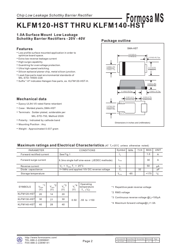
KLFM130-HST Key Features
- 2 Mechanical data
- 2 Maximum ratings
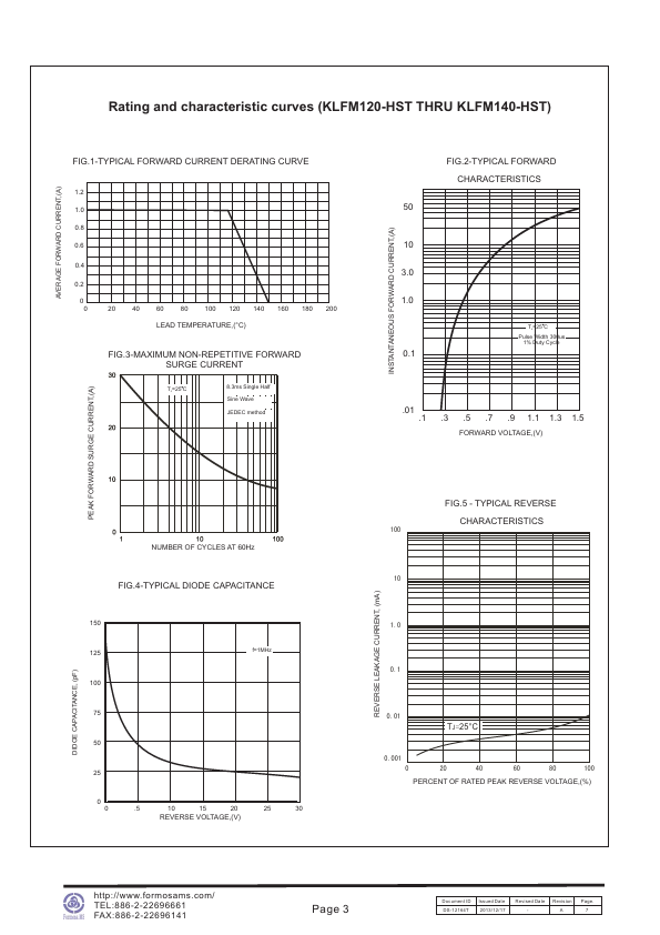
- 2 Rating and characteristic curves
- 3 Pinning information
- 4 Marking
- 4 Suggested solder pad layout
- 4 Packing information