Part number:
BZX84C16
Manufacturer:
Fairchild Semiconductor
File Size:
166.60 KB
Description:
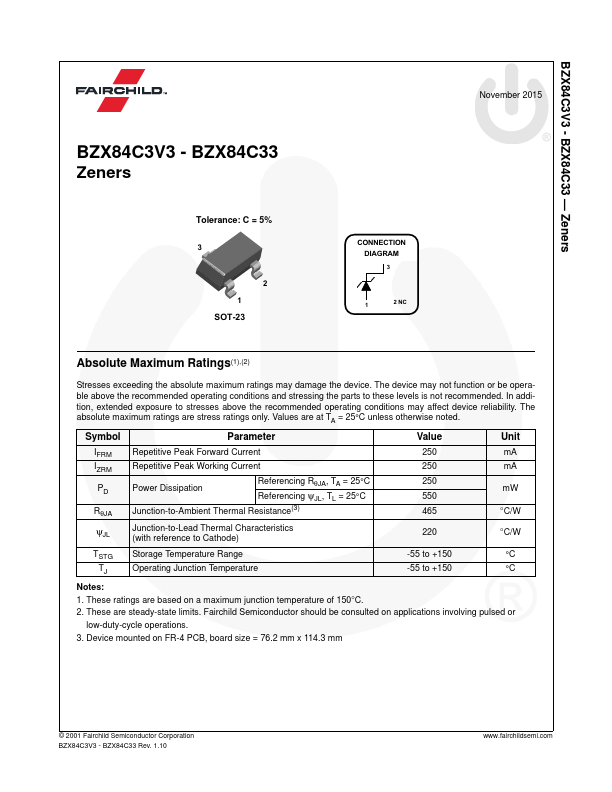
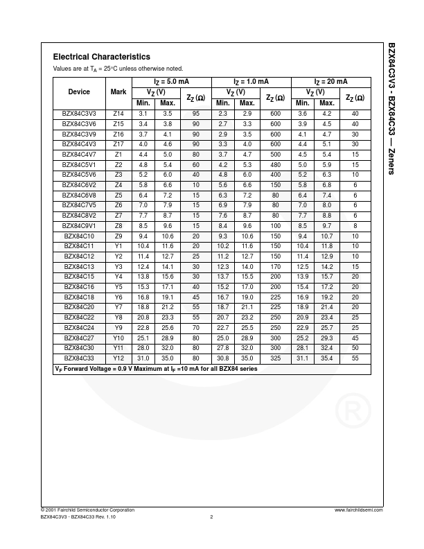
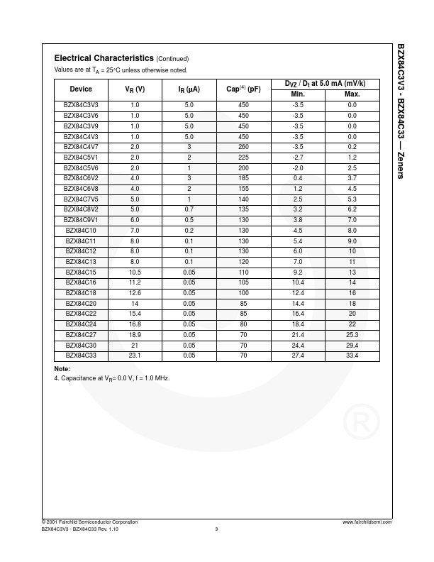
Zeners.
BZX84C16 Datasheet (166.60 KB)
Datasheet Details
BZX84C16
Fairchild Semiconductor
166.60 KB
Zeners.
📁 Related Datasheet
BZX84C10 Zeners (Fairchild Semiconductor)
BZX84C10 Surface Mount Zener Diodes (GOOD-ARK)
BZX84C10 Surface Mount Silicon Planar Zener Diodes (Diotec Semiconductor)
BZX84C10 Small Signal Zener Diodes (Vishay)
BZX84C10 350mW SURFACE MOUNT ZENER DIODE (WON-TOP)
BZX84C10 350mW SURFACE MOUNT ZENER DIODE (Diodes)
BZX84C10 Silicon Planar Zener Diodes (JGD)
BZX84C10 SILICON PLANAR ZENER DIODES (SEMTECH)
BZX84C16 Distributor