EUP3482
EUP3482 is 340KHz Synchronous Step-Down Converter manufactured by Eutech Microelectronics.
2A, 30V, 340KHz Synchronous Step-Down Converter
DESCRIPTION
The EUP3482 is a synchronous current mode buck regulator capable of driving 2A continuous load current with excellent line and load regulation. The EUP3482 can operate with an input range 4.5V to 30V and the output can be externally set from 0.923V to 20V with a resistor divider. Fault condition protection includes cycle-by-cycle current limiting and thermal shutdown. In shutdown mode the regulator draws 1µA of supply current. Programmable soft-start minimizes the inrush supply current and the output overshoot at initial startup. The EUP3482 require a minimum number of external ponents.
Features
2A Output Current 220ns Minimum On Time 35V Input Surge Protection Integrated 160mΩ/110mΩ DMOS Switches 4.5V to 30V Input Operating Range Output Adjustable from 0.923V to 20V Up to 95% Efficiency 1µA Shutdown Current Fixed 340KHz Frequency Programmable Soft-Start Thermal Shutdown and Overcurrent Protection Input Supply Overvoltage and Undervoltage Lockout Available in SOP-8 Package Ro HS pliant and 100% Lead(Pb)-Free Halogen-Free
APPLICATIONS
Vm
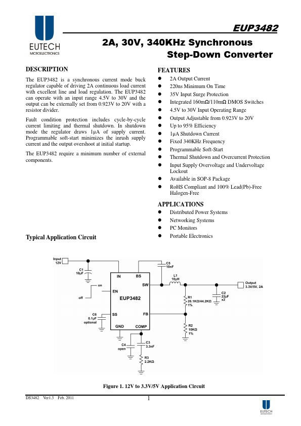
Typical Application Circuit
R w‘ yb om c . ch w
.g w w te o f o
Distributed Power Systems Networking Systems PC Monitors Portable Electronics
Figure 1. 12V to 3.3V/5V Application Circuit
DS3482 Ver1.3 Feb. 2011
N~- NªtmæW3^Vmw‘Rybg PQl Sł
Tel: 0755-8398 3377 / 135 9011 2223 http://.gofotech.
Typical Application Circuit (continued)
Figure2. 24V to 3.3V/5V Application Circuit
Pin Configurations
Package Type Pin Configurations
SOP-8
Vm
Pin Description
PIN 1 2 3 4 5 6 7 8
DS3482 Ver1.3
R w‘ yb t .co h c e m ofo g . w ww
PIN NAME BS IN SW GND FB P EN SS
Feb. 2011
DESCRIPTION
High-Side Gate Drive Boost Input. BS supplies the drive for the high-side N-Channel DMOS switch. Connect a 0.01µF or greater capacitor from SW to BS to power the high side switch. Input Supply Pin. IN supplies the power to the IC, as well as the step-down...