SBR1045SP5
Overview
- Designed as Bypass Diodes for Solar Panels Selectively Rated for 200ºC Maximum Junction Temperature for High Thermal Reliability Patented Super Barrier Rectifier Technology Low Forward Voltage Drop Excellent High Temperature Stability Lead Free Finish, RoHS Compliant (Note 2) Mechanical Data * * * * * *
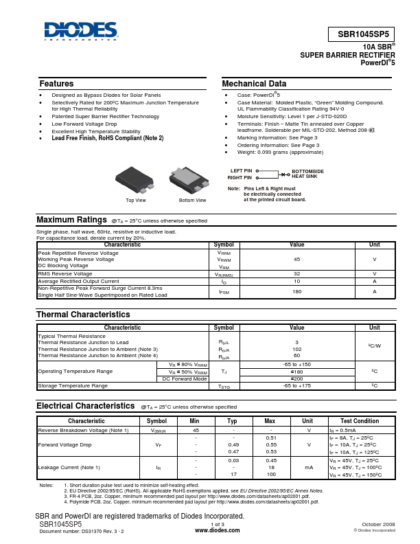
- Case: PowerDI 5 Case Material: Molded Plastic, “Green” Molding Compound. UL Flammability Classification Rating 94V-0 Moisture Sensitivity: Level 1 per J-STD-020D Terminals: Finish - Matte Tin annealed over Copper leadframe. Solderable per MIL-STD-202, Method 208 Marking Information: See Page 3 Ordering Information: See Page 3 Weight: 0.093 grams (approximate) ®