QSOP-20 Description
2 Surface Mount Package Case Material: Molded Plastic, UL Flammability Rating 94V-0 Terminals: Finish - Matte Tin Plated Leads, Solderable per MIL-STD-202, Method 208 e3 Weight:.
QSOP-20 is PACKAGE manufactured by Diodes Incorporated.
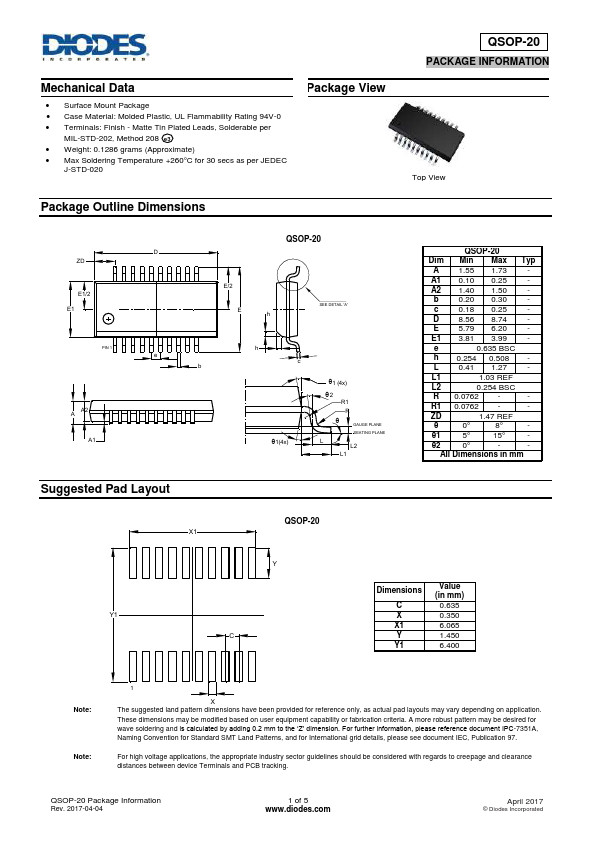
2 Surface Mount Package Case Material: Molded Plastic, UL Flammability Rating 94V-0 Terminals: Finish - Matte Tin Plated Leads, Solderable per MIL-STD-202, Method 208 e3 Weight:.