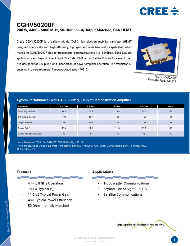
Absolute Maximum Ratings (not simultaneous)
Parameter
Symbol
Rating
Drain-Source Voltage
Gate-to-Source Voltage
Storage Temperature
Operating Junction Temperature
VDSS
125
VGS
10, +2
TSTG
-65, +150
TJ
225
Maximum Forward Gate Current
Maximum Drain Current1
Soldering Temperature2
Screw Torque
IGMAX
IDMAX
TS
τ
41.6
17
245
40
Thermal Resistance, Junction to Case
RθJC
0.81
Case Operating Temperature3
TC
-40, +125
Note:
1 Current limit for long term, reliable operation
2 Refer to the Application Note on soldering at http://www.cree.com/rf/document-library
3 See also, Power Dissipation Derating Curve on page 12
Electrical Characteristics
Units
Volts
Volts
˚C
˚C
mA
A
˚C
in-oz
˚C/W
˚C
Conditions
25˚C
25˚C
25˚C
25˚C
CW, 85˚C, PDISS = 166.4 W
Characteristics
Symbol
Min.
Typ.
DC Characteristics1 (TC = 25˚C)
Gate Threshold Voltage
VGS(th)
-3.4
-3.0
Gate Quiescent Voltage
VGS(Q)
–
-2.7
Saturated Drain Current2
IDS
33.28
37.4
Drain-Source Breakdown Voltage
VBR
150
–
RF Characteristics3 (TC = 25˚C, F0 = 4.4 - 5.0 GHz unless otherwise noted)
Small Signal Gain
GSS1
14
15.4
Small Signal Gain
GSS2
14
15.3
Small Signal Gain
GSS3
14.25
15.2
Power Gain4
GP1
10.5
12.1
Power Gain4
GP2
10.5
12.4
Power Gain4
GP3
10.5
12.2
Power Added Efficiency4
PAE1
30
42
Power Added Efficiency4
PAE2
30
37
Power Added Efficiency4
PAE3
30
40
OQPSK Linearity4
ACLR1
–
-29
OQPSK Linearity4
ACLR2
–
-34
OQPSK Linearity4
ACLR3
–
-34
Max.
-2.6
–
–
–
–
–
–
–
–
–
–
–
–
-25
-28
-26
Output Mismatch Stress
VSWR
–
–
3:1
Notes:
1 Measured on wafer prior to packaging.
2 Scaled from PCM data.
3 Measured in CGHV50200F-AMP
4 Measured under 1.6 Msps OQPSK Modulation, PN23, Alpha Filter = 0.2
Units Conditions
VDC
VDS = 10 V, ID = 41.6 mA
VDC
VDS = 40 V, ID = 1.0 A
A
VDS = 6 V, VGS = 2 V
VDC
VGS = -8 V, ID = 41.6 mA
dB
VDD = 40 V, ID = 1.0 A, PIN = 10 dBm, Freq = 4.4 GHz
dB
VDD = 40 V, ID = 1.0 A, PIN = 10 dBm, Freq = 4.8 GHz
dB
VDD = 40 V, ID = 1.0 A, PIN = 10 dBm, Freq = 5.0 GHz
dB
VDD = 40 V, ID = 1.0 A, POUT = 48 dBm, Freq = 4.4 GHz
dB
VDD = 40 V, ID = 1.0 A, POUT = 48 dBm, Freq = 4.8 GHz
dB
VDD = 40 V, ID = 1.0 A, POUT = 48 dBm, Freq = 5.0 GHz
%
VDD = 40 V, ID = 1.0 A, POUT = 48 dBm, Freq = 4.4 GHz
%
VDD = 40 V, ID = 1.0 A, POUT = 48 dBm, Freq = 4.8 GHz
%
VDD = 40 V, ID = 1.0 A, POUT = 48 dBm, Freq = 5.0 GHz
dBc
VDD = 40 V, ID = 1.0 A, POUT = 48 dBm, Freq = 4.4 GHz
dBc
VDD = 40 V, ID = 1.0 A, POUT = 48 dBm, Freq = 4.8 GHz
dBc
VDD = 40 V, ID = 1.0 A, POUT = 48 dBm, Freq = 5.0 GHz
No damage at all phase angles,
Y
VDD = 40 V, ID = 1.0 A, CW POUT = 180 W
Copyright © 2013 - 2019 Cree, Inc. All rights reserved. The information in this document is subject to change without notice. Cree and the Cree logo are
registered trademarks of Cree, Inc.
2
CGHV50200F Rev 3.0
Cree, Inc.
4600 Silicon Drive
Durham, North Carolina, USA 27703
USA Tel: +1.919.313.5300
Fax: +1.919.869.2733
www.cree.com/RF