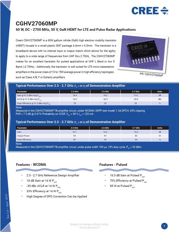
Absolute Maximum Ratings (not simultaneous) at 25˚C Case Temperature
Parameter
Symbol
Drain-Source Voltage
VDSS
Gate-to-Source Voltage
VGS
Storage Temperature
TSTG
Operating Junction Temperature
TJ
Maximum Forward Gate Current
IGMAX
Maximum Drain Current1
IDMAX
Soldering Temperature2
TS
Thermal Resistance, Junction to Case3
RθJC
Thermal Resistance Pulsed 10%, 100 μs, Junction to Case
Case Operating Temperature4
RθJC
TC
Note:
1 Current limit for long term, reliable operation.
2 Refer to the Application Note on soldering at http://www.cree.com/rf/document-library
3 Measured for the CGHV27060MP
4 See also, the Power Dissipation De-rating Curve on Page 4.
Electrical Characteristics (TC = 25˚C)
Rating
150
-10, +2
-65, +150
225
10.4
6.3
245
2.6
1.95
-40, +90
Units
Volts
Volts
˚C
˚C
mA
A
˚C
˚C/W
˚C/W
˚C
Conditions
25˚C
25˚C
25˚C
25˚C
85˚C, PDISS = 52 W
85˚C, PDISS = 62W, 100 μs/10%
CW
Characteristics
DC Characteristics1
Symbol
Min.
Typ.
Max.
Units
Conditions
Gate Threshold Voltage
VGS(th)
-3.8
Gate Quiescent Voltage
VGS(Q)
–
Saturated Drain Current2
IDS 8.4
Drain-Source Breakdown Voltage
VBR 150
RF Characteristics5 (TC = 25˚C, F0 = 2.7 GHz unless otherwise noted)
Saturated Output Power3,4
PSAT
–
-3.0
-2.7
10.4
–
80
-2.3
–
–
–
–
VDC VDS = 10 V, ID = 10.4 mA
VDC VDS = 50 V, ID = 125 mA
A VDS = 6.0 V, VGS = 2.0 V
VDC VGS = -8 V, ID = 10.4 mA
W VDD = 50 V, IDQ = 125 mA
Pulsed Drain Efficiency3,4
η – 70 – % VDD = 50 V, IDQ = 125 mA, POUT = PSAT
Gain3,4
G
– 16.5 –
dB VDD = 50 V, IDQ = 125 mA, POUT = PSAT
Gain6
G
– 18.5 –
dB VDD = 50 V, IDQ = 125 mA, POUT = 41.5 dBm
WCDMA Linearity6
ACLR
–
-35
–
dBc VDD = 50 V, IDQ = 125 mA, POUT = 41.5 dBm
Drain Efficiency6
Output Mismatch Stress3
Dynamic Characteristics
η
VSWR
–
–
34 –
% VDD = 50 V, IDQ = 125 mA, POUT = 41.5 dBm
– TBD Y No damage at all phase angles, VDD = 50 V, IDQ =
125 mA, POUT = 60 W Pulsed
Input Capacitance7
CGS – 15.3 – pF VDS = 50 V, Vgs = -8 V, f = 1 MHz
Output Capacitance7
CDS – 4.7 – pF VDS = 50 V, Vgs = -8 V, f = 1 MHz
Feedback Capacitance
CGD – 0.5 – pF VDS = 50 V, Vgs = -8 V, f = 1 MHz
Notes:
1 Measured on wafer prior to packaging.
2 Scaled from PCM data.
3 Pulse Width = 100 µs, Duty Cycle = 10%
4 PSAT is defined as IGS = 1.0 mA peak
5 Measured in CGHV27060MP-TB.
6 Single Carrier WCDMA, 3GPP Test Model 1, 64 DPCH, 45% Clipping, PAR = 7.5 dB @ 0.01% Probability on CCDF, VDD = 50 V.
7 Includes package.
Copyright © 2015-2016 Cree, Inc. All rights reserved. The information in this document is subject to change without notice. Cree and the Cree logo are
registered trademarks of Cree, Inc.
2 CGHV27060MP Rev 1.1
Cree, Inc.
4600 Silicon Drive
Durham, North Carolina, USA 27703
USA Tel: +1.919.313.5300
Fax: +1.919.869.2733
www.cree.com/rf