• Part: KBU606-G
  • Description: Silicon Bridge Rectifiers
  • Manufacturer: Comchip
  • Size: 96.33 KB
Download KBU606-G Datasheet PDF
KBU606-G page 2
Page 2
KBU606-G page 3
Page 3

KBU606-G Datasheet Text

Silicon Bridge Rectifiers KBU6005-G Thru. KBU610-G Reverse Voltage: 50 to 1000V Forward Current: 6.0A RoHS Device Features -Surge overload rating - 175 amperes peak. -Ideal for printed circuit board. -Plastic material has U/L flammability classification 94V-0 0.
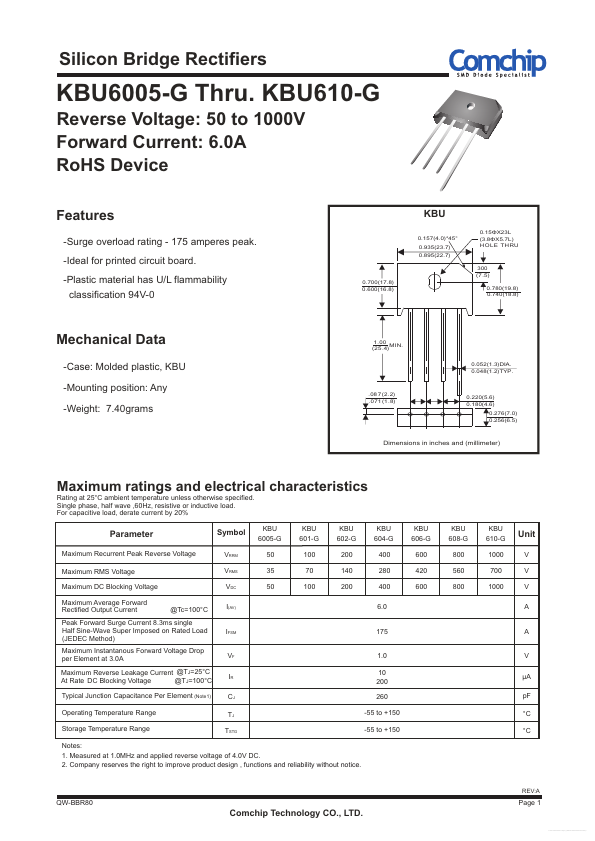
700(17.8) 0.600(16.8) KBU 0.157(4.0)- 45° 0.935(23.7) 0.895(22.7) 0.15ΦX23L (3.8ΦX5.7L) HOLE TH RU 300 (7 .5) 0.780(19.8) 0.740(18.8) Mechanical Data -Case: Molded plastic, KBU -Mounting position: Any -Weight: 7.40grams 1.00 MIN. (25 .4) 0.052(1.3)DIA. 0.048(1.2)TYP. .08 7 (2.2) .0 71 (1 .8) 0.220(5.6) 0.180(4.6) 0.276(7.0) 0.256(6.5) Dimensions in inches and (millimeter) Maximum ratings and electrical characteristics Rating at 25°C ambient temperature unless otherwise specified. Single phase, half wave ,60Hz, resistive or inductive load. For capacitive load, derate current by 20% KBU 6005-G 50 35 50 KBU 601-G 100 70 100 KBU 602-G 200 140 200 KBU 604-G 400 280 400 6.0 KBU 606-G 600 420 600 KBU 608-G 800 560 800 KBU 610-G 1000 700 1000 Parameter Maximum Recurrent Peak Reverse Voltage Maximum RMS Voltage Maximum DC Blocking Voltage Maximum Average Forward Rectified Output Current @Tc=100°C Symbol VRRM VRMS VDC I(AV) Unit V V V A Peak Forward Surge Current 8.3ms single Half Sine-Wave Super Imposed on Rated Load (JEDEC Method) Maximum Instantanous Forward Voltage Drop per Element at 3.0A Maximum Reverse Leakage Current @TJ=25°C At Rate DC Blocking Voltage @TJ=100°C Typical Junction Capacitance Per Element (Note1) Operating Temperature Range Storage Temperature Range IFSM VF IR CJ TJ TSTG 175 1.0 10 200 260 -55 to +150 -55 to +150 A V μA pF °C °C Notes: 1. Measured at 1.0MHz and applied reverse voltage of 4.0V DC. 2. pany reserves the right to improve product design , functions and reliability...