CS10S280CT-A Overview
Key Features
- Low forward voltage drop
- Excellent high temperature stability
- Fast switching capability
- Lead-free parts meet environmental standards of MIL-STD-19500 /228
- Mechanical data
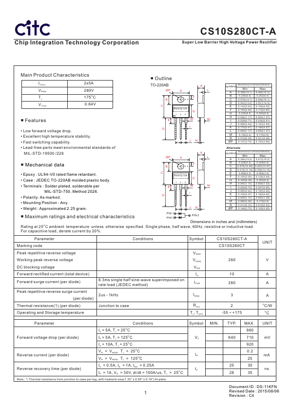
| Part | CS10S280CT-A |
|---|---|
| Description | Super Low Barrier High Voltage Power Rectifier |
| Manufacturer | Chip Integration Technology |
| Size | 455.88 KB |
| Part Number | Manufacturer | Description |
|---|---|---|
| IRLZ44N | International Rectifier | Power MOSFET |
| IRF540 | International Rectifier | HEXFET POWER MOSFET |
| SS14 | Vishay | Surface Mount Schottky Barrier Rectifier |