Chip Integration Technology Corporation
C40S100CT
40A Trench Schottky Rectifier
Main Product Characteristics
IF(AV)
VRRM
TJ
VF(Typ)
2 X 20A
100V
150OC
0.615V
■ Features
• Low forward voltage drop.
• Excellent high temperature stability.
• Fast switching capability.
• Lead free in compliance with EU RoHS.
■ Mechanical Data
• Epoxy : UL94-V0 rated flame retardant.
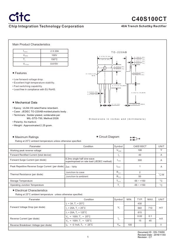
• Case : JEDEC TO-220AB molded plastic body .
• Terminals : Solder plated, solderable per
MIL-STD-750, Method 202. 6
• Polarity: As marked.
• Weight : Approximated 2.25 gram.
TO-220AB
0.419(10.66)
0.387(9.85)
0.139(3.55)
MIN
0.269(6.85)
0.226(5.75)
0.196(5.00)
0.163(4.16)
0.054(1.39)
0.045(1.15)
0.624(15.87)
0.548(13.93)
0.038(0.96)
0.019(0.50)
0.177(4.50)MAX
0.50(12.70)MIN
0.1(2.54)
0.025(0.65)MAX
Dimensions in inches and (millimeters)
■ Maximum Ratings
Rating at 25OC ambient temperature unless otherwise specified.
■ Circuit Diagram
Parameter
Working peak reverse voltage
Forward Rectified Current (total device)
Forward Surge Current (per diode)
Condition
Symbol
V RWM
8.3ms single half sine-wave
superimposed on rate load (JEDEC method)
IO
IFSM
Peak Repetitive Reverse Surge Current (per diode) 2us - 1kHz
IRRM
Thermal Resistance (per diode)
Storage Temperature
Operating Junction Temperature
Junction to case
Junction to ambient
■ Electrical Characteristics
Rating at 25OC ambient temperature unless otherwise specified.
RθJC
RθJA
TSTG
TJ
Parameter
Forward Voltage Drop (per diode)
Reverse Current (per diode)
Reverse Breakdown Voltage (per diode)
Condition
IF = 3A, TJ = 25OC
IF = 20A, TJ = 25OC
IF = 20A, TJ = 125OC
VR = 100V, TJ = 25OC
VR = 100V, TJ = 125OC
IR = 0.1mA, TJ = 25OC
Symbol
VF
IR
VBR
C40S100CT
100
40
300
1
2
50
-55 ~ +150
-55 ~ +150
MIN.
100
TYP.
430
640
615
0.02
15
MAX.
710
0.1
45
UNIT
V
A
A
A
OC/W
OC
OC
UNIT
mV
mA
V
Document ID : DS-11KEK
Revised Date : 2016/11/03
1 Revision : C7