• Part: ADP1110
  • Description: Step-Up/Step-Down Switching Regulator
  • Manufacturer: Analog Devices
  • Size: 420.60 KB
Download ADP1110 Datasheet PDF
ADP1110 page 2
Page 2
ADP1110 page 3
Page 3

ADP1110 Datasheet Text

Micropower, Step-Up/Step-Down Switching a Regulator; Adjustable and Fixed 3.3 V, 5 V, 12 V ADP1110 Features Operates at Supply Voltages From 1.0 V to 30 V Step-Up or Step-Down Mode Minimal External ponents Required Low-Battery Detector User-Adjustable Current Limiting Fixed or Adjustable Output Voltage Versions 8-Pin DIP or SO-8 Package APPLICATIONS Cellular Telephones Single-Cell to 5 V Converters Laptop and Palmtop puters Pagers Cameras Battery Backup Supplies Portable Instruments Laser Diode Drivers Hand-Held Inventory puters FUNCTIONAL BLOCK DIAGRAMS SET ADP1110 A2 VIN GAIN BLOCK/ ERROR AMP 220mV REFERENCE A1 OSCILLATOR A0 ILIM SW1 Q1 PARATOR R2 R1 300kΩ DRIVER GND SENSE SW2 ADP1110 Block Diagram- Fixed Output Version SET ADP1110 GENERAL DESCRIPTION 
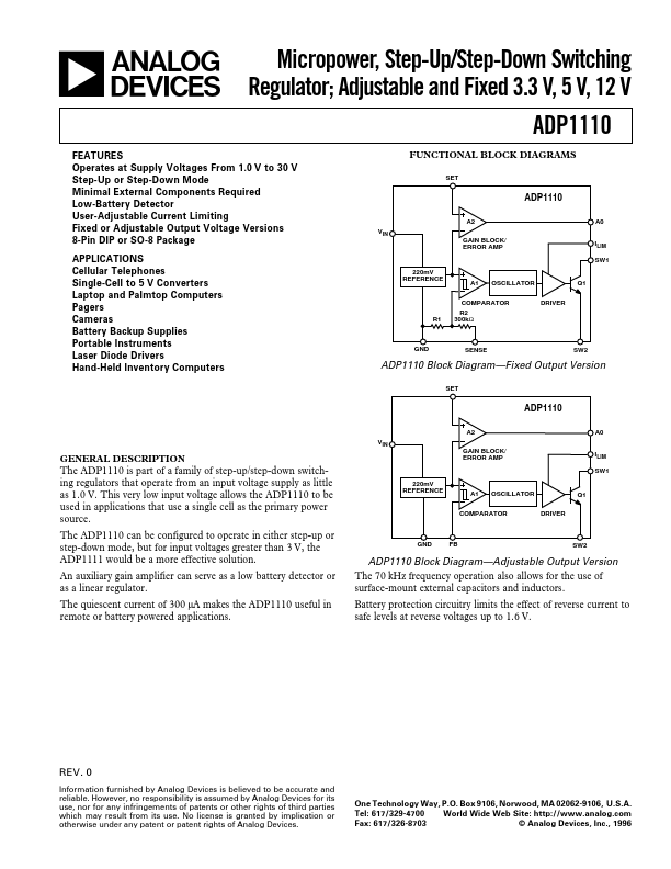
The ADP1110 is part of a family of step-up/step-down switching regulators that operate from an input voltage supply as little as 1.0 V. This very low input voltage allows the ADP1110 to be used in applications that use a single cell as the primary power source. The ADP1110 can be configured to operate in either step-up or step-down mode, but for input voltages greater than 3 V, the ADP1111 would be a more effective solution. An auxiliary gain amplifier can serve as a low battery detector or as a linear regulator. The quiescent current of 300 µA makes the ADP1110 useful in remote or battery powered applications. A2 VIN GAIN BLOCK/ ERROR AMP 220mV REFERENCE A1 OSCILLATOR...