Datasheet Details
| Part number | ASSR-1420 |
|---|---|
| Manufacturer | AVAGO |
| File Size | 308.62 KB |
| Description | Solid State Relay |
| Datasheet |
 ASSR-1420 Datasheet ASSR-1420 Datasheet
|
|
|
Download the ASSR-1420 datasheet PDF. This datasheet also covers the ASSR-1410 variant, as both devices belong to the same solid state relay family and are provided as variant models within a single manufacturer datasheet.
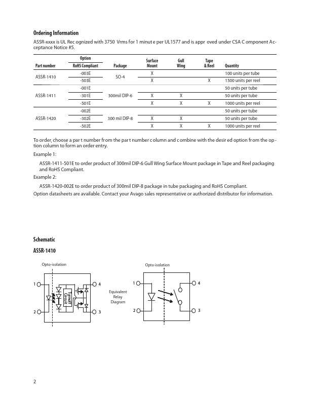
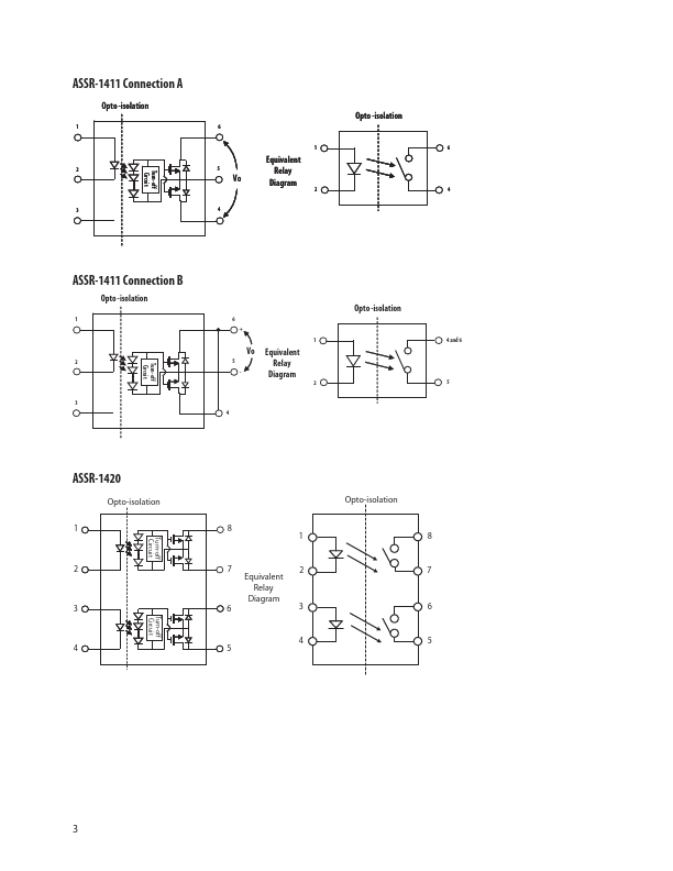
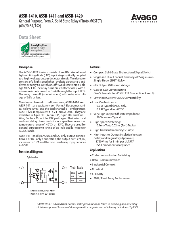
The ASSR-14X X S eries c onsists of an AlG aAs infrar ed light-emitting diode (LED) input stage optically coupled to a high-v oltage output det ector circuit.
The det ector consists of a high-speed phot ovoltaic diode arra y and driver circuitry to switch on/off t wo discrete high v oltage MOSFETs.
| Part number | ASSR-1420 |
|---|---|
| Manufacturer | AVAGO |
| File Size | 308.62 KB |
| Description | Solid State Relay |
| Datasheet |
ASSR-1420 Datasheet
|
|
|
|
| Part Number | Description | Manufacturer |
|---|---|---|
| ASSR-1420 | Solid State Relay | Broadcom |
| ASSR-1410 | Solid State Relay | Broadcom |
| ASSR-1411 | Solid State Relay | Broadcom |
| ASSR-1218 | Solid State Relay | Broadcom |
| ASSR-1219 | Solid State Relay | Broadcom |
| Part Number | Description |
|---|---|
| ASSR-1410 | Solid State Relay |
| ASSR-1411 | Solid State Relay |
| ASSR-1218 | Solid State Relay |
| ASSR-1219 | Solid State Relay |
| ASSR-1228 | Solid State Relay |
The following content is an automatically extracted verbatim text from the original manufacturer datasheet and is provided for reference purposes only.