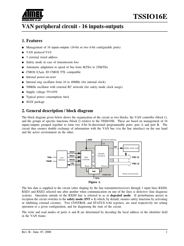
Datasheet4U Logo Datasheet4U.com

TSS-IO16-E - Van Peripheral Circuit - 16 Inputs-outputs

Download the TSS-IO16-E datasheet PDF. This datasheet also covers the TSSIO16E variant, as both devices belong to the same van peripheral circuit - 16 inputs-outputs family and are provided as variant models within a single manufacturer datasheet.

Description

The block diagram given below shows the organization of the circuit as two blocks: the VAN controller (block 1), and the groups of specific functions (block 2) relative to the TSSIO16E.

Features

  • q q q q q q q q q q q q Management of 16 inputs-outputs (16-bit or two 8-bit configurable ports) VAN protocol V4.0 3 external wired address Safety mode in case of transmission loss Automatic adaptation to speed of bus from 8kTS/s to 250kTS/s CMOS 0,5µm, IO CMOS TTL compatible Internal power-on-reset Internal ring oscillator from 10 to 40MHz (for internal clock) 500kHz oscillator with external RC network (for safety mode clock usage) Supply voltage 5V±10% Typical power consomption 4mA SO28 packa.

📥 Download Datasheet

Note: The manufacturer provides a single datasheet file (TSSIO16E_ATMELCorporation.pdf) that lists specifications for multiple related part numbers.

Full PDF Text Transcription (Reference)

The following content is an automatically extracted verbatim text from the original manufacturer datasheet and is provided for reference purposes only.

View original datasheet text
TSSIO16E VAN peripheral circuit - 16 inputs-outputs 1. Features q q q q q q q q q q q q Management of 16 inputs-outputs (16-bit or two 8-bit configurable ports) VAN protocol V4.0 3 external wired address Safety mode in case of transmission loss Automatic adaptation to speed of bus from 8kTS/s to 250kTS/s CMOS 0,5µm, IO CMOS TTL compatible Internal power-on-reset Internal ring oscillator from 10 to 40MHz (for internal clock) 500kHz oscillator with external RC network (for safety mode clock usage) Supply voltage 5V±10% Typical power consomption 4mA SO28 package 2. General description / block diagram The block diagram given below shows the organization of the circuit as two blocks: the VAN controller (block 1), and the groups of specific functions (block 2) relative to the TSSIO16E.
Published: |